
Welcome to the Network Engineering Domain
Pape O. Fall's Blog
In this post, we will look into setting up MPLS VPN and use EIGRP as our routing protocol between the PE router and the CE router. We won’t go deeper into the MPLS VPN backbone configuration but just the PE-CE segment. At this point, if you are unfamiliar with MPLS VPN, please read this post here.
Also note that typically, EIGRP is not going to be what you’ll typically see in a real environment as PE-CE routing protocol due to its limitations in terms of platform compatibility.
To be consistent, we will use the same MPLS diagram we’ve been using…
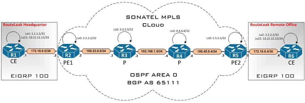
MPLS is fully configured except the links between the PEs and the CEs. We will configure EIGRP AS 1 on the PE routers and note that RouteLeak offices will run EIGRP AS 100. Let’s hop on the consoles and configure our PE routers…
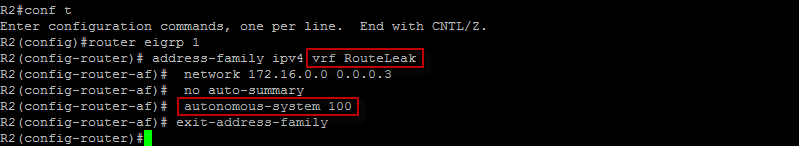
Here, notice how we have to specify the AS number that the CE router at the customer side is running. If not, the adjacency will not come up. We also need to specify the VRF context for this peering which is RouteLeak. Also, we have disabled auto summarization here because it could cause the same summary being propagated across multiple distinct sites that are based on network class. Let’s do the same on the other side…
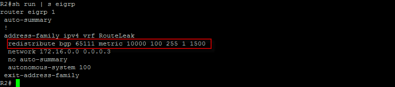
Good ! Our next step is now to redistribute BGP into EIGRP at the PE routers…
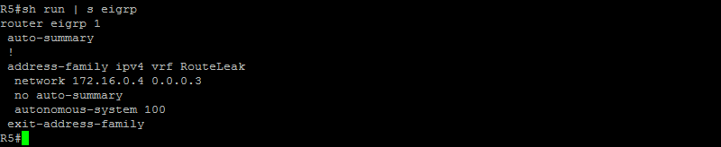
All right, let’s do the same on the other side…

Good ! Since we have redistributed BGP into EIGRP, we now need to redistribute EIGRP into BGP on both sides. Let’s do that…
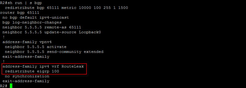
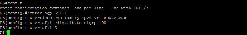
Here, under the VRF context we have redistributed EIGRP into BGP. Let’s do the same on the other side…
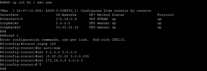
All right ! We should be done with the PE routers. Let’s hop on the CE routers and configure EIGRP AS 100, disable auto summarization and advertise our networks into the routing protocol…

Pretty straight forward here as we have configure EIGRP AS 100 and advertised our networks, let’s do the same on the other side…
Great ! Let’s now check the routing table of the CE router at the HeadQuarter…
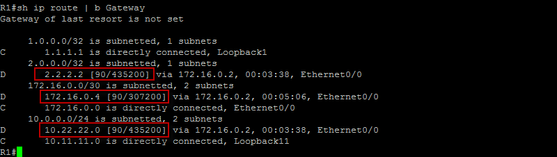
Good ! here we can clearly see EIGRP internal routes coming from Eth0/0. Let’s see if we can ping and trace the other side…
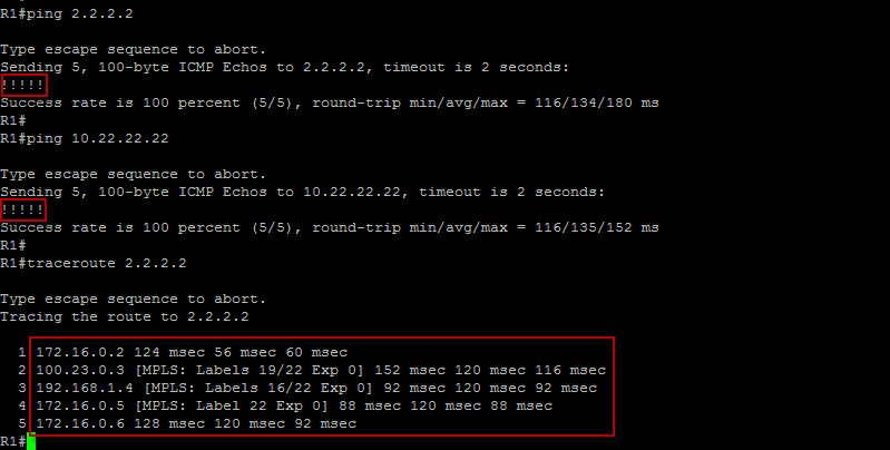
Very good ! We can clearly see the path to the loopback on the far side as well as the labels geenrated by LDP. Let’s look at the routing table on the PE routing under VRF RouteLeak…
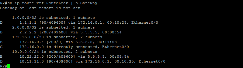
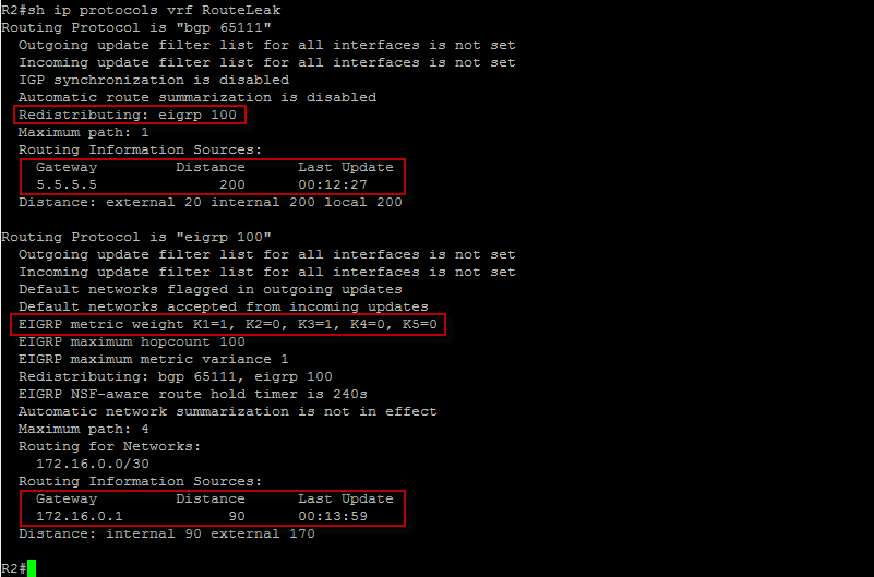
Notice how the far side prefixes appear as iBGP routes with an admin distance of 200. That’s because the routes have been redistributed into BGP. Let’s check the routing protocols running for VRF RouteLeak…
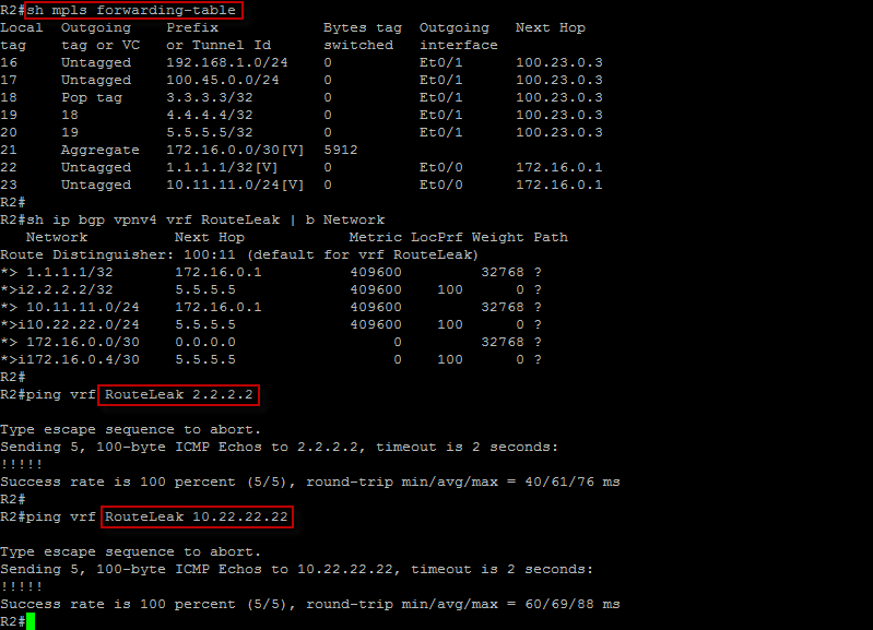
Let’s now check our MPLS forwarding table and make sure we can ping across…
That’s all for this topic. Please leave me a comment if you have any questions.
 Hi, I'm Pape ! Folks call me Pop. I'm CCIE #48357. I love what I do and enjoy making tech easier to understand. I also love writing, so I’m sharing my blog with you
| M | T | W | T | F | S | S |
|---|---|---|---|---|---|---|
| 1 | ||||||
| 2 | 3 | 4 | 5 | 6 | 7 | 8 |
| 9 | 10 | 11 | 12 | 13 | 14 | 15 |
| 16 | 17 | 18 | 19 | 20 | 21 | 22 |
| 23 | 24 | 25 | 26 | 27 | 28 | 29 |
| 30 | ||||||
Hi Pape,
I hope that you’re quite well.
Thank you for this article, it is very helpful and well explained.
Please allow me to ask a few question.
1) In this example the same AS 100 is running in both sites and the routes appear at each site as EIGRP internal (AD 90).
– Can R1 form an EIGRP neighbour adjacency with R6? or this would only be possible if the link PE-CE were in the same AS?
– Does R1 send routing updates to R6, for instance, if a node fail in site 1, this message would be advertised to R6?
– The metrics shown in R1 routing table takes into consideration the costs associated in the BGP domain?
2) Assuming that site 1 was using EIGRP AS 100 and site 2 using EIGRP AS 200.
– The AD would change to EIGRP external (AD 170)?
– Is there any benefits of using different AS in different sites? If so, what would be the relevant change in the configurations?
3) Can you explain the purpose of the following command.
redistribute bgp 65111 metric 10000 100 255 1 1500
Thank you in advance.
Best Regards,
Muhammad Adil
Hello Mr. Adil,
-R1 is actually forming an EIGRP peering session with R6 in this lab and that’s the reason you are able to ping the loopback of R6 from R1. R1 is also sending route advertisement to R1. The MPLS backbone is the transport that makes the advertisement available. Please read my blog about MPLS L3 VPN in order to understand how the transport network is built first.
-R1 here is only running EIGRP and there would be 2 metrics in play here in terms of route advertisement via EIGRP and that’s internal and external admin distance (90 & 170).
-One of the requirement to form a EIGRP peering session is that the AS number has to match.
-That command allows you to redistribute BGP into EIGRP. Please watch my blog about redistribution.