
Welcome to the Network Engineering Domain
Pape O. Fall's Blog
In this post, we will look into setting up MPLS VPN and use OSPF as our routing protocol between the PE router and the CE router. We won’t go deeper into the MPLS VPN backbone configuration but just the PE-CE segment. At this point, if you are unfamiliar with MPLS VPN, please read this post here.
To be consistent, we will use the same MPLS diagram we’ve been using…
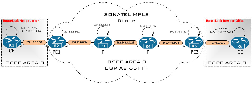
MPLS is fully configured except the links between the PEs and the CEs. Let’s hop on the consoles and configure our PE routers…

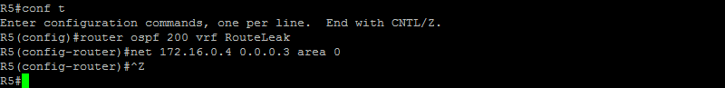
Notice how we have to specify the appropriate VRF when enabling the routing protocol. Remember, we are using OSPF 1 inside the MPLS VPN backbone. Here, we also have OSPF 200 to peer with RouteLeak offices. Let’s do the same on the other side…
Our next step is now to redistribute BGP into OSPF. Let’s do that on the PE router at the HeadQuarter office…
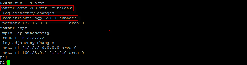
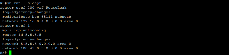
As stated earlier, notice how we have 2 OSPF instances running at this point. OSPF 1 is for the MPLS VPN backbone. Let’s do the same on the other side…
Let’s now redistribute OSPF into BGP on both sides…
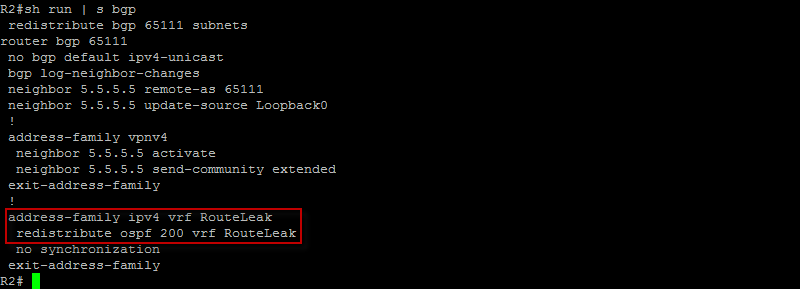
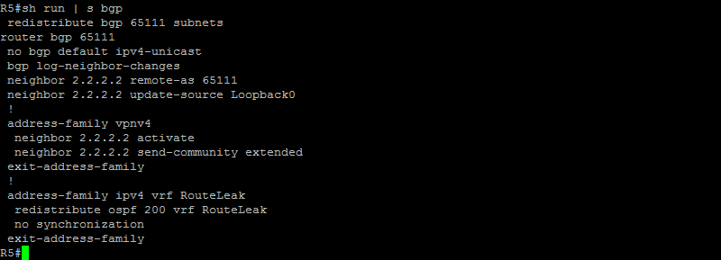
Good ! Under vrf context RouteLeak, we have redistributed OSPF process ID 200 into BGP. Let’s do the same at the remote side…
Good ! Let’s now get on the CE routers to configure OSPF process ID 9 and advertise our networks into the routing protocol…
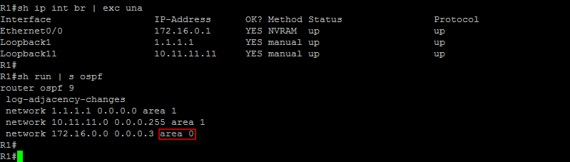
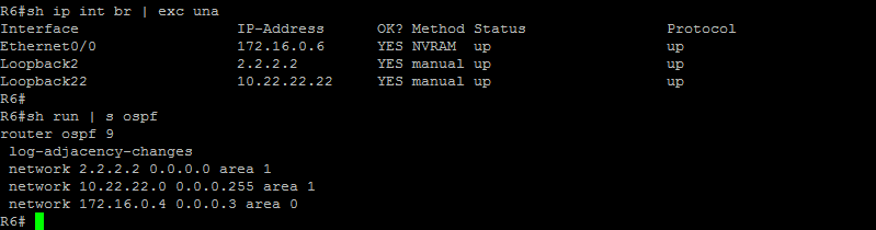
Here, we have the /30 link between the PE router and the CE router in area 0. We have purposely advertised our networks in area 1. Let’s do the same on the other side…
Good ! Let’s now check the routing table on the CE router at the HeadQuarter office…
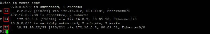
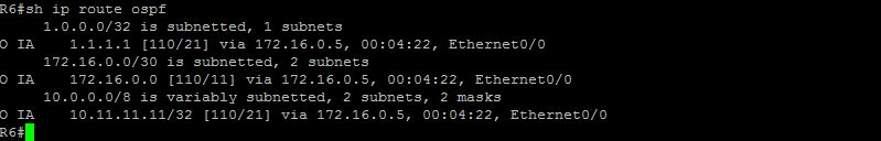
Very good ! We are seeing the networks at the remote side as OSPF inter-area routes. Let’s check the routing table on the other side as well…
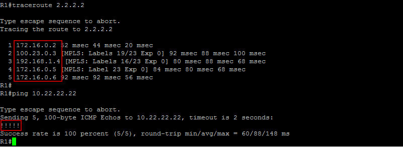
Let’s make sure we can trace and ping across. We should see all routers in the transit path…
This is good ! Let’s check our routing table for VRF RouteLeak on the PE router at the HeadQuarter…
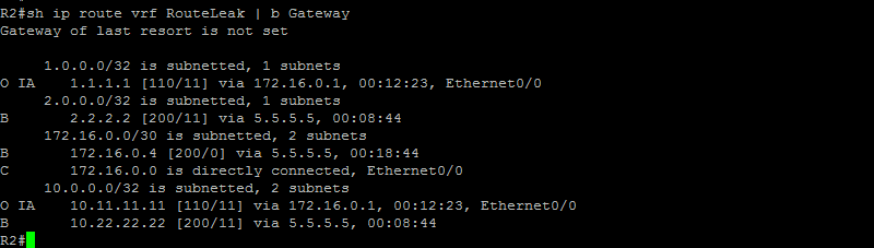
Very good ! All routes are there. Let’s check our MPLS forwarding table and the IP protocol for VRF RouteLeak…
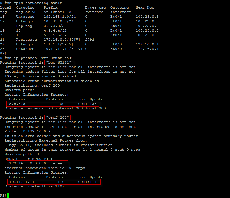
Here we can clearly see the labels generated by LDP and useful information about the routing protocols being used such as the network being advertised, whether or not there are filters associated with the protocol, the process ID and so on… Note that the process ID does not have to be same on both sides in order to establish adjacency.
That’s all I have today. Please leave me a comment if you have any questions…
 Hello I'm Pape. My friends call me Pop. I'm CCIE #48357. I enjoy my field and love to share it with others. I love to write so I'm sharing my blog with you.
| M | T | W | T | F | S | S |
|---|---|---|---|---|---|---|
| 1 | ||||||
| 2 | 3 | 4 | 5 | 6 | 7 | 8 |
| 9 | 10 | 11 | 12 | 13 | 14 | 15 |
| 16 | 17 | 18 | 19 | 20 | 21 | 22 |
| 23 | 24 | 25 | 26 | 27 | 28 | 29 |
| 30 | ||||||
Leave a Reply