
Welcome to the Network Engineering Domain
Pape O. Fall's Blog
OSPF is a routing protocol providing dynamic adjacency capabilities. It is a Link State protocol and is mostly used as IGP in large entreprise networks. Another Link State protocol is IS-IS which is still used in certain circumstances such as on the MPLS core of a Service Provider network… Also, the underline protocol running “TRILL” which is the technology replacing STP is IS-IS; The same goes for “FabricPath” but we can touch on that at a later time. Some of the characteristics of OSPF is that as a Link State protocol, it keeps a full topology of your network. You can already guess that the downside of this approach is the fact that it is ultimately a bit more cpu intensive as opposed to a Distance Vector protocol per say. The upside of this protocol however is that it knows all of the best path to a given destination which prevents in essence routing loops. For this section, we will use the following topology…

In an OSPF environment, a DR (Designated Router) and a (Backup Designated Router) selection needs to occur providing the network is a Multi-Access segment. The reason for it is because in OSPF, Link State Routers exchange what’s called LSA (Link State Advertisements) which are used to build a database called LSDB (Link State Database). Consider LSDB as the full topology of the network which is used by the router to calculate the shortest path to a destination using the shortest-path first (SPF) algorithm. Now imagine that you have a network which consist of let’s say 150 routers… All Link State routers would flood their LSA to other routers in order to build the LSDB. Can you visualize the amount of OSPF traffic just to build the topology ? To remediate that issue, a DR is selected and all OSPF router forms an adjacency with the DR and flood their LSA directly to the DR. The DR then propagates it across all other routers. That way, we have far less OSPF traffic and adjacency requirements. The BDR serves as a backup in case the DR fails.
Note that in a point-to-point type network, a DR and BDR selection does not take place.
Here, you can also notice the different areas isolating the network into different domain. In OSPF, you have what’s called a backbone area wich is typically Area 0. All other areas MUST connect to the backbone area somehow. If you have for instance area 1 which needs to talk to area 2, well they will need to go through the backbone area (Area 0). Other areas are called “Standard Areas”.
Note that an area router keeps a full topology of the network it resides in. This helps calculate the shortest path faster in a large scale network.
A router in the backbone area (area 0) is called a backbone router.
A router between 2 distinct areas such as “Transit 2” in our example is called a ABR (Area Border Router).
A router running OSPF which connects to another router running another routing protocol is called ASBR (Autonomous System Border Router)
There is one particularity in OSPF we’ll need to go through and it is the fact that there are certain parameters within the hello packets that need to match on both side in order for an adjacency to occur. Once the routers are neighbors, hello packets are sent in order to form an adjacency. The following are the fields that’d need to match on both side:
Subnet Mask: Subnet Mask of the interface peering with the opposite link state router
Area-id: The area where the router resides
Hello Timer: Time interval to send hello packets
Dead Timer: Hold time when a hello packet is not received
Network type: Point-to-Point, Broadcast, and Non-Broadcast. We’ll go though these in a sec
Value of the stub area flag: We’ll go though this in a sec
Authentication: If configured, the password needs to be the same
Let’s discuss some of the different network types. So we have:
-Point-to-Point
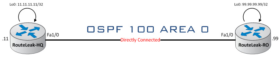
Typically, you would set the network type as Point-to-Point on a directly connected segment. No DR or BDR election required here. If you have a network with multiple Point-to-Point links, each segment will be in a different IP address range.
-Point-to-Multipoint
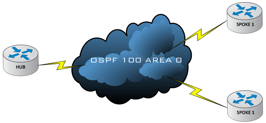
Here, the nonbroadcast network is treated as a collection of point-to-point links. No DR or BDR election required here. Since these are considered as point-to-point links, they can all be part of a common subnet (In a DMVPN network for instance).
-Broadcast
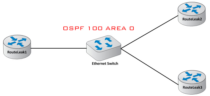
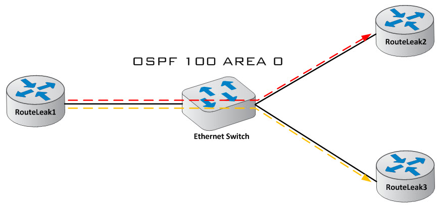
Here, multicast will be used to discover OSPF neighbors dynamically. The default network type for an Ethernet segment is Broadcast. DR and BDR selection process does occur.
-Nonbroadcast
Here, OSPF hellos, LSAs, LSUs are individually transmitted as unicast packets. This is typically used on Networks that has neither broadcast nor multicast capability such as Frame Relay, ATM, SMDS, & X.25 (Even though we almost don’t see them anymore). DR and BDR selection process does occur.
Let’s touch on Stub Areas now…
A stub area is mainly characterized by an area which has a single exit point and typically via default route. Let’s say you are peering with a sea vessel in the middle of the Atlantic ocean which has a single exit point to a shore office via Satellite communications. The router onboard the vessel could be configured as a stub in this case as well as the interface facing the vessel at the shore office. Note that external networks such as redistributed routes from a different routing protocol are not allowed to be flooded into a stub area. It is important to note that all OSPF routers inside a stub area have to be configured as stub routers because all interfaces inside the stub area will exchange hello packets with a special flag indicating that the interface is stub. On top of stub areas, we have “Totally Stubby Area” and “Not-so-Stubby Area”.
Totally Stubby Area: So a stub area says basically “Hey, I don’t want to receive external routes since I have a default route”. A “Totally Stubby Area” says “Hey, Don’t send me external routes as well as any other routes”. So basically, just the default route will do.
Not-so-Stubby Area: Well, let’s say we buy an oil platform which is running RIP and we needed to temporarily connect it to our vessel via Satellite then back out the default route to our shore office. Since the vessel is a Stub area, then external routes are not permitted by default, right ? So the Not-so-Stubby feature allows the platform routes to go through the stub area and appears as external routes at the shore office. Basically Type 7 going in and Type 5 going out. Oops ! We haven’t talked about the LSA types yet ! Let’s do that…
We’ve talked about how OSPF uses LSAs to build the LSDB. It just happens that OSPF actually uses many different type of LSAs and here they are:
LSA Type 1 – Router LSA which is generated by default whenever a link state router is added to the network
LSA Type 2 – Network LSA for the DR (Designated Router). The LSA is generated to inform link state routers the whereabouts of the DR
LSA Type 3 – Summary LSAs which are generated by ABR (Area Border Router) whenever traffic goes from one area to another
LSA Type 4 – Summary LSA for the ASBR (Autonomous System Border Router). The LSA is generated to inform link state routers the whereabouts of the ASBR
LSA Type 5 – External LSAs to propagate routes from the network behind the ASBR
LSA Type 7 – This is used in certain corner cases where there’s a network behind a stub router running a different protocol for instance. Type 7 LSA is used to instruct the ASBR to convert the advertisement to type 5 LSA and flood the rest of the network
All right, let’s hop onto the consoles now and see everything in action…
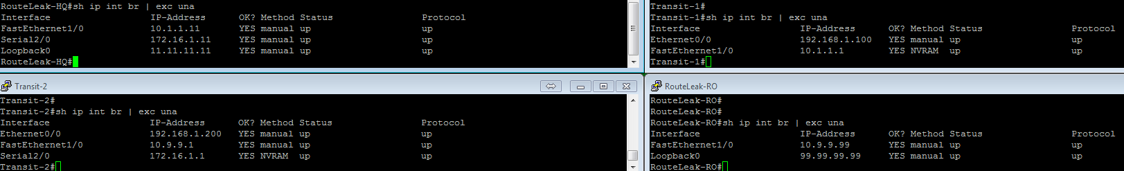
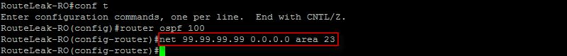
As you can see here, all IP addresses are pre-configured. Let’s configure the OSPF process…
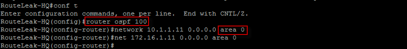
Here, we used the command “router ospf 100” to enable the OSPF process where 100 is the process ID. We have also used the network command to define which interface will run OSPF as well as the area ID. Note that right after the network prefix, we have the wildcard mask which is “0.0.0.0” in our case indicating a match for the /32 prefix.
Let’s configure the OSPF process on Transit 1…
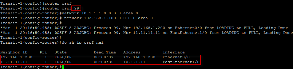
Here, I wanted to show you something… Have you noticed how the process ID on Transit 1 is different from Routeleak-HQ OSPF Process ID ? Here we have 99 as a Process ID and we have 100 at the HeadQuarter and yet the neighbor relationship still formed and the adjacencies came up with both RouteLeak-HQ and Transit 2. That’s because the Process ID in OSPF is locally significant unlike in EIGRP for instance. The only time the OSPF process ID is taken into account is when OSPF is leveraged as the routing protocol on a PE (Provider Edge) to CE (Customer Edge) link in a MPLS VPN network. All right, let’s move on !
Typically, when configuring OSPF it is always best practice to manually configure the router-ID for several reason. A router ID is fundamental for the OSPF process to start. The IOS must be able to identify a unique OSPF router ID (32-bit) via the following sequential process:
-Use arbitrary router-ID if statically configured
-Use the highest IPv4 address of all active loopback interfaces on the router
-Use the highest IPv4 address among all active nonloopback interfaces
Let’s configure OSPF on all routers and check our neighbor relationship…
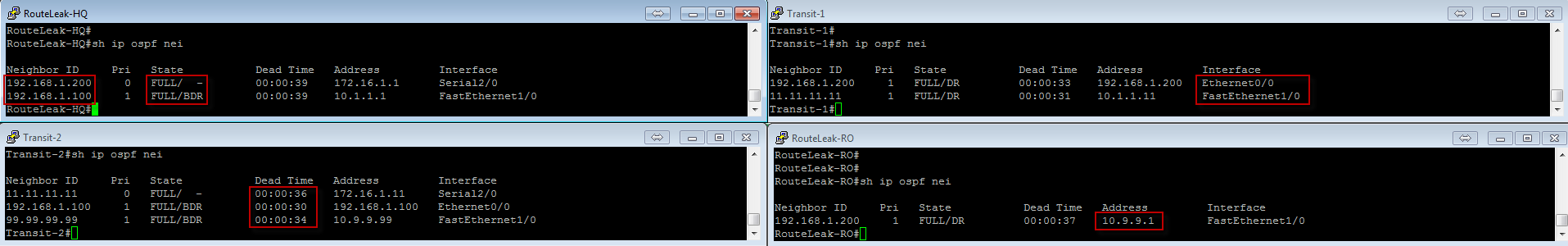
Here we have issued the “show ip ospf neighbor” command which displays the neighbor relationship on a per interface basis.
Neighbor ID: This represent the neighbor router ID. Noticed how the highest loopback interface is selected as a router ID for RouteLeak-HQ and since we do not have loopback interfaces for Transit 1 and Transit 2, the highest interface IP addresses have been selected for both
Priority: This is the priority on the neighbor interface. This is used for DR/BDR election
State: “Full” here means that the local router has now full adjacency with the remote peer. “DR” or “BDR” denotes that the election process has been completed and that Transit 2 is the DR on its segment.
Dead Time: When the time expires, the router terminates the neighbor relationship. the timer is reset whenever a hello packet is received
Address: Primary IPv4 address of the neighbor router
Interface: Local interface over which an OSPF adjacency is established
The output of the “show ip ospf interface …” command displays very useful information. Let’s see what we have from RouteLeak-HQ perspective…
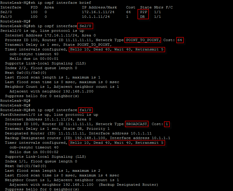
Noticed how the state of the serial interface section is “P2P”. That’s because by default, the link is considered as Point-to-Point link. Noticed how the cost (64) is less attractive than the FastEthernet’s ? If you look at the output of the “sh ip ospf nei” above with Transit 2, you will see that there is no DR/BDR election process as this is a Point-to-point link. We also have the OSPF parameter values which need to match in order to establish full adjacency. The network type is displayed as well as the DR and BDR info.
The output of the “show ip route ospf” displays the ospf leaned routes. let’s do that…
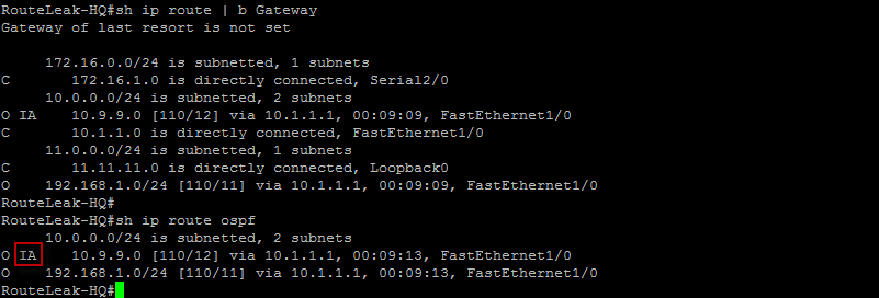
Notice how 10.9.9.0 is marked as IA. So in OSPF you have certain routes that are marked as either Inter-Area or Intra-Area routes. Here is the main difference between the two:
*Inter-Area: Inter-Area routes are originated from different OSPF area (Area 23 in our case here) and advertised into the current area from the router’s perspective. Inter-Area routes are advertised with LSA type 3.
*Intra-Area: Intra-Area routes are originated and learned in the same area from the router’s perspective. LSA type 1 and 2 are used to advertise intra-Area routes.
At this point, we have adjacencies across our network. Let’s look at some stub scenarios. Let’s inject our loopback prefix into OSPF on RouteLeak-HQ via redistribution..

Good ! Let’s now advertise the loopback at the Remote Office into OSPF…
All right ! Let’s now check what we have…
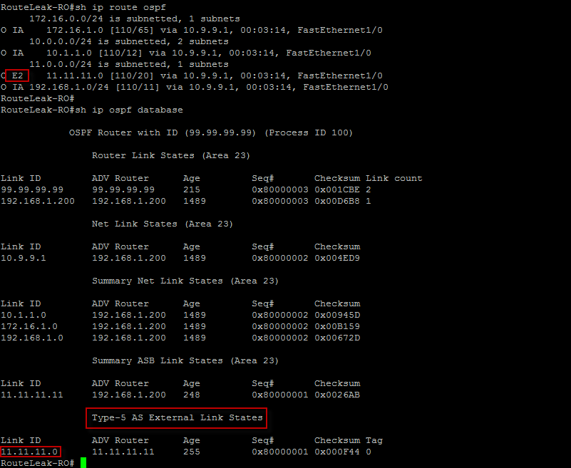
From the HeadQuarter perspective, RouteLeak-RO loopback will be marked as a IA route as it has been advertised via Area 23. But from RouteLeak-RO perspective, notice how a Type 5 external LSA have been generated for the loopback address as it has been redistributed. Note that the cost remains 20 and does not increment. Let’s now make Area 23 a stub area and see what we get…

Let’s now check the routing table again as well as the OSPF database…
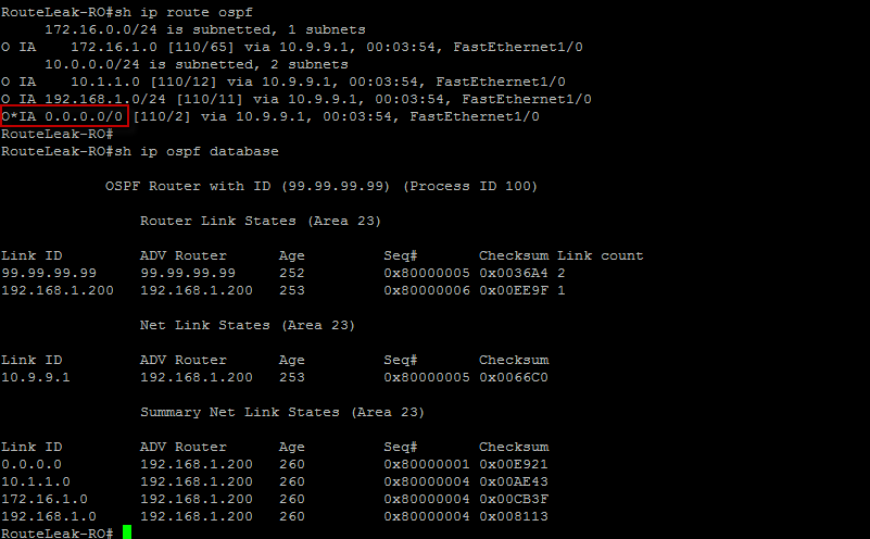
All right, here we can see that the external route is now gone. Remember we’ve established that stub areas do not allow external routes. This is perfectly normal. Here, we can see the inter-area routes in the routing table and the database is much smaller. Notice also how a default route has been injected by the ABR when configuring the area as a stub.
Let’s configure Area 23 as Totally Stubby and see what we get…

Let’s see what we have…
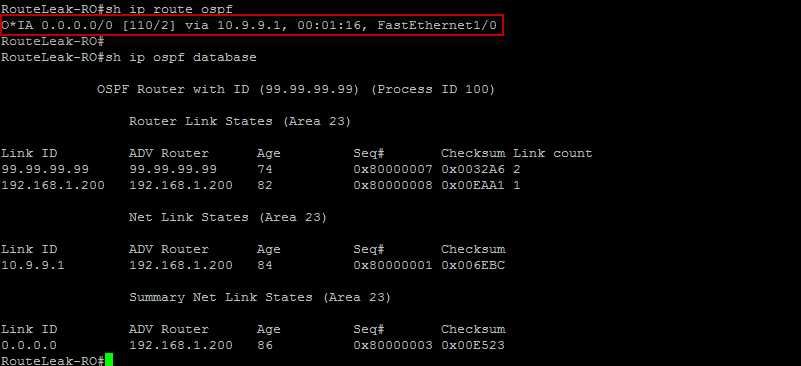
This validates what we’ve discussed about “Totally Subby” areas. The Inter-Area routes are gone and we only have the default route in our main routing table. So, basically LSA type 3 and type 5 are not allowed here.
Let’s now make Area 23 a Not-so-Stubby Area…

Let’s now remove the advertisement of the loopback prefix and inject it into OSPF via redistribution…
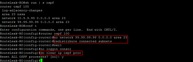
Here, we have remove the network command for the loopback prefix and redistributed the loopback into OSPF. Notice how we needed to clear the OSPF process here to reset the adjacency and update the database and routing table. Let’s see what we have from the Remote office perspective…
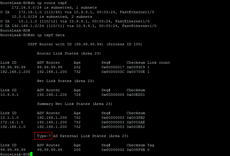
Here a type 7 external LSA has been generated. Let’s take a look at Transit 2…

Transit 2 also has a type 7 external LSA in the LSDB since it is in the same area as RouteLeak-RO. But have you noticed how it also generated a type 5 external LSA to flood it into area 0 ? This still validates what we have discussed about NSSA.
Let’s look at area 0 and see if the prefix has been received with a Type 5 external LSA for the loopback prefix…
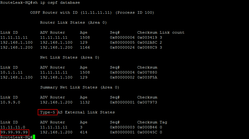
Sure enough, it is there ! Type 5 LSA has been generated for the loopback prefix in Area 0.
NB: OSPF SPF is an interrupt driven process and it uses 100% of the CPU capacity.
That completes this topic… Take care.
 Hello I'm Pape. My friends call me Pop. I'm CCIE #48357. I enjoy my field and love to share it with others. I love to write so I'm sharing my blog with you.
| M | T | W | T | F | S | S |
|---|---|---|---|---|---|---|
| 1 | ||||||
| 2 | 3 | 4 | 5 | 6 | 7 | 8 |
| 9 | 10 | 11 | 12 | 13 | 14 | 15 |
| 16 | 17 | 18 | 19 | 20 | 21 | 22 |
| 23 | 24 | 25 | 26 | 27 | 28 | 29 |
| 30 | ||||||
Leave a Reply