
Welcome to the Network Engineering Domain
Pape O. Fall's Blog
IS-IS is a Link State IGP that’s fairly similar to OSPF in terms of operations. In fact, they were created around the same time ! IS-IS stands for Intermediate System to Intermediate System. In essence, an “Intermediate Systems” simply means a “Router”. So, “Router to Router” is a fair analogy when describing the protocol. Typically IS-IS is used in Service Provider core networks due to its simplicity and scalability which provide the ability to design a flat highly mesh network that supports both IPv4 and IPv6 routing simultaneously.
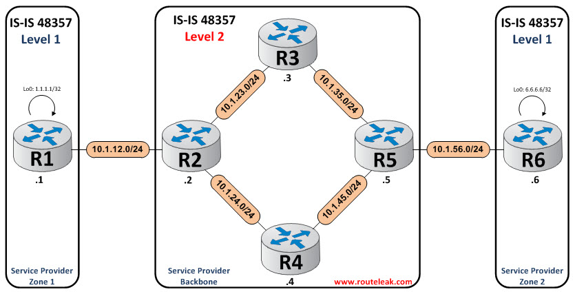
For the purpose of this topic, we will use the following topology…
Let’s first iron out the different features in regards to the protocol.
IS-IS routers exchange information about the network topology via the use of special packets called Link State PDU (Link State Protocol Data Units). Similar to OSPF, the information received is stored in the Link State Database. The shortest path is also calculated using the Dijkstra shortest-path first (SPF) algorithm. Note that IS-IS actually runs directly on the Data Link layer (Layer 2) unlike other routing protocol. This implies that 2 interfaces running IS-IS do not require IP addresses to exchange information.
One key difference to take into account here is that IS-IS was developed as part of the OSI network protocols called CLNS as opposed to the TCP/IP stack. It was then later extended to support IP routing and the new version was then called Integrated IS-IS.
IS-IS uses what’s called “NET” (Network Entity Title), which can vary from 8 to 20 bytes long, to denote its IS or router in the overall topology per say. “NET” is similar to “Router-ID” in OSPF.
3 characteristics make up the IS-IS NET format:
Example – AA.AAAA.AAAA.AAAA.AAAA.AAAA.AAAA.SSSS.SSSS.SSSS.NN
*Area Identifier: IP address space that is assigned to an autonomous system. This is not the “Area” like in OSPF which demarc a SPF flooding domain.
*System-ID: Router ID inside the area. It necessarily need to be unique inside its area.
*N-Selector: Always zero
Another aspect of IS-IS to remember is that it has two “levels” of adjacency:
*Level 1 (L1): This is similar to OSPF non-backbone area. It only supports Intra Area adjacency similar to a nssa area in OSPF.
*Level 2 (L2): This is similar to OSPF area 0. It supports both Inter and Intra Area adjacency and must be contiguous.
By default, interfaces in a given segment form 2 distinct adjacency (L1 & L2) which results in 2 different LSP databases. Hence, double the overhead !
Also, it is important to note that we only have 2 network types in IS-IS which are “Broadcast” and “Point-to-Point”. A Designated Intermediate System is elected in broadcast format to reduce the amount of flooding in a LSP segment (Similar to DR in OSPF).
Let’s hop onto the consoles and configure our topology !
At this point, All segments have been pre-configured with their respective IP subnets. Let’s start with the configuration of R1 and R2…
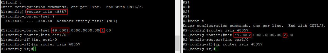
Here, the “router isis process ID” enable the protocol globally. Note that the process ID here is locally significant (similar to OSPF) and not a requirement. Once the protocol is enabled globally, the command “ip router isis process ID” activate the protocol on the interfaces running IS-IS.
If a process ID is defined under the isis process, it needs to be specified at the interface level as well. If no process ID is configured, you would just need the command “ip router isis” at the interface level.
Here, we’ve also specified the “Area Identifier” as 49.0001 for the level 1 flooding domain and 49.0002 for the level 2 flooding domain. Let’s now check and see if we have an adjacency…
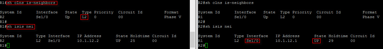
Both the “show clns is-neighbors” and the “show isis neighbors” display similar information is terms of adjacency. Notice here that the adjacency type is “level 2” simply because R1 is in area 49.0001 and R2 is in 49.0002. The state of the session is “Up” which is what we want and we can also see the peering interface which is Ser1/0.
Let’s configure the intra adjacencies between R2, R3, R4 and R5 in area 49.0002. Since they are in the same area domain, we should see both L1 and L2 type adjacency. Let’s do that…
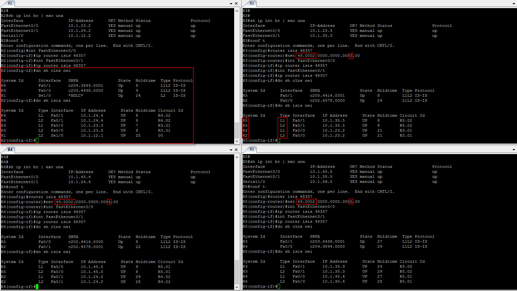
Observe here how we have both L1 and L2 type for each session. This is because we have configure a singular area ID in the ISP core network. So we clearly have adjacency across. Let’s now configure the inter adjacency between R5 and R6 per our diagram…
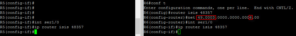
Okay good ! Let’s configure and advertise our loopback addresses and check the routing table of both R1 and R6…
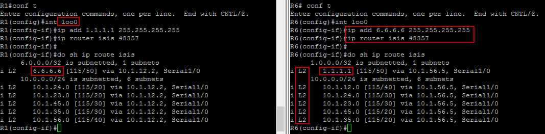
Here we can clearly see the loopback prefixes in both routing table. At this point, we should be able to ping the opposite loopback address from either R1 or R6. Let’s do that…

We have now full adjacency across… Let’s now check the database table for R2 for instance…
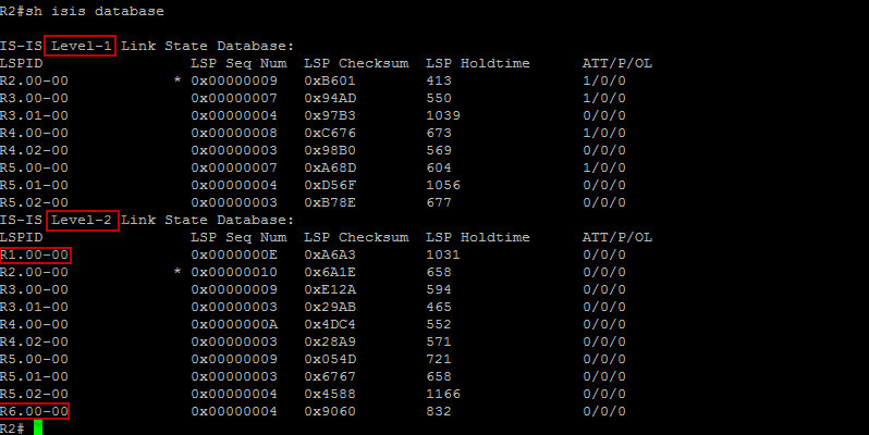
Notice here how the output of the database table displays both L1 and L2 Link State Database. R2 L1 database outputs only routers in its area
but R2 L2 database not only shows routers that are in its area but also routers that are in different areas.
Generating the same entries for both L1 and L2 database does not typically scale as it just results in extra overhead. If you look closely, R2, R3, R4 and R5 entries are present in both database type outputs. Since, the Link State packets for the routers in both databases are the same, let’s fix the issue on all routers by running a single level adjacency between the routers.
We have 2 options here:
1) Configure “is-type” under the global process. This option affect all interfaces and would not be suitable for a router running both L1 and L2.
2) Configure “isis circuit-type” at the interface level. This option is suitable for a router running both L1 and L2.
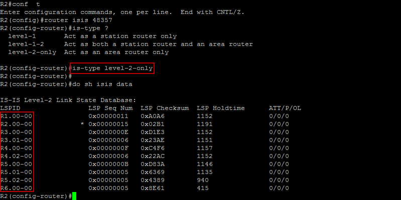
We can see here that the database shrinked and eradicated the duplicates which is what we want. The same need to be configured on all routers.
If we were the check the neighbor relationship on R2 now, we’d see that only L2 type neighbor sessions will only be maintained. Let’s do that…
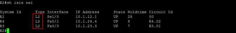
Here are couple of troubleshooting commands we can run when dealing with IS-IS…
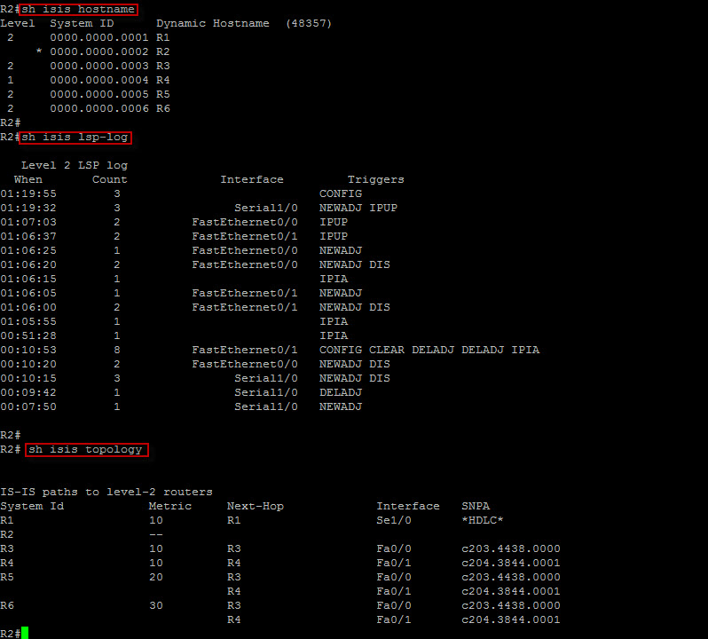
The “show isis hostname” displays the router-name-to-system-IS mapping table.
The “show isis lsp-log” displays the L1 and L2 IS-IS Link State packet (LSP) log of the interfaces that triggered the new LSP.
The command “show isis topology” displays a list of all connected routers in all areas.
That completes this topic. Thank you for checking in !
 Hi, I'm Pape ! Folks call me Pop. I'm CCIE #48357. I love what I do and enjoy making tech easier to understand. I also love writing, so I’m sharing my blog with you
| M | T | W | T | F | S | S |
|---|---|---|---|---|---|---|
| 1 | 2 | 3 | 4 | |||
| 5 | 6 | 7 | 8 | 9 | 10 | 11 |
| 12 | 13 | 14 | 15 | 16 | 17 | 18 |
| 19 | 20 | 21 | 22 | 23 | 24 | 25 |
| 26 | 27 | 28 | 29 | 30 | 31 | |
I think everyone might use a tad bit more of the information.
Thank you !
When I originally commented I clicked the “Notify me when new comments are added” checkbox and
now each time a comment is added I get several emails with the same
comment. Is there any way you can remove people from that service?
Thank you!
Hello Rene,
I’ll tweak the settings. Let me know if you receive more emails. Thank you for letting me know though.
bookmarked!! I love your site!
Man! this is one of the best IS-IS explanations with clear examples I have ever come across. Many Thanks for educating us