
Welcome to the Network Engineering Domain
Pape O. Fall's Blog
MPLS (Multiprotocol Label Switching) is technology which allows fast packet forwarding using “Labels” within a given network. VPN (Virtual Private Network) is then implemented to provide a connected oriented service by ensuring end-to-end reachability between non directly connected nodes. At this point, if you are unfamiliar with MPLS then please read the first portion of this post here explaining in details how MPLS works.
As the topic indicates, we are focusing on MPLS L2 VPN which emulates the characteristics of a LAN across an IP or MPLS enabled network allowing Ethernet devices to communicate with each other as if they were part of the same LAN segment.
At this point, you should have a basic understanding of how MPLS works… If not, please read the MPLS L3 VPN post.
For the sake of this topic, we will use the following topology.
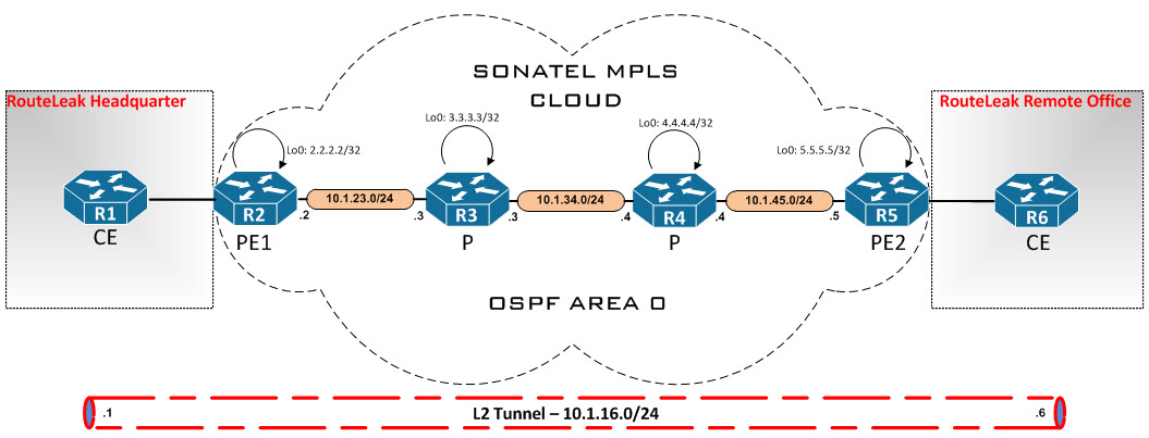
Here, we have an ISP called SONATEL which connects both RouteLeak HQ and RO via their MPLS backbone. Let’s hop on the consoles now and configure our backbone here…
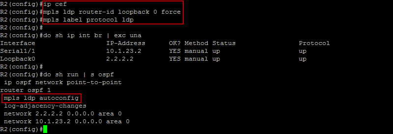
All right ! We have our IP addresses in ! OSPF is configured and enabled on the interfaces per the diagram and MPLS is enabled on all interfaces running OSPF. Let’s do the same on R3, R4 and R5…
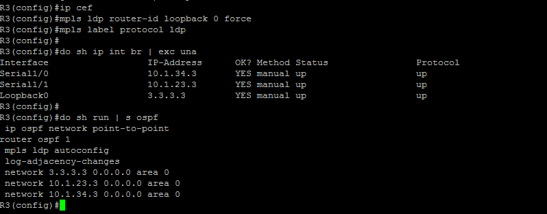
All right ! R3 is good ! Let’s move on to R4…

R4 is good ! Let’s run the same commands on R5…
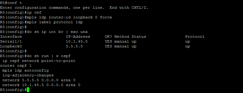
Excellent ! Let’s run some verification commands and make sure we are solif end-to-end…
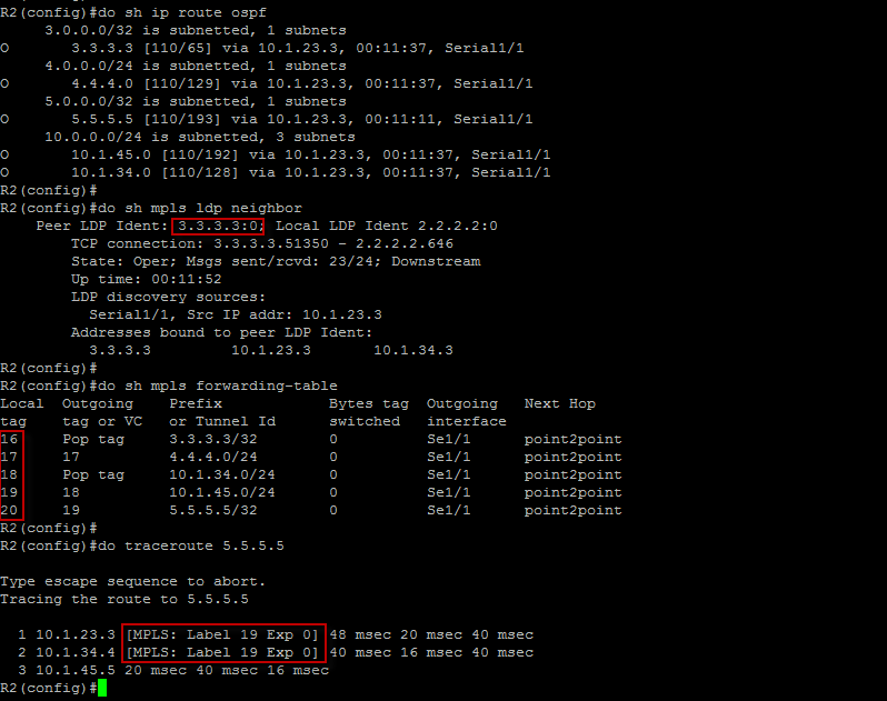
Excellent ! Here we can clearly see that we have IGP routes to our LDP sources (Loopback 0) and we also have a 1-to-1 correlation between each routing entry and the local tag number. We can also see the label switch mechanism in the traceroute output. I’ve gone ahead and verified R3, R4 and R5 as well. Let’s now configure our CE (Customer Edge) devices…
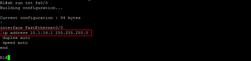
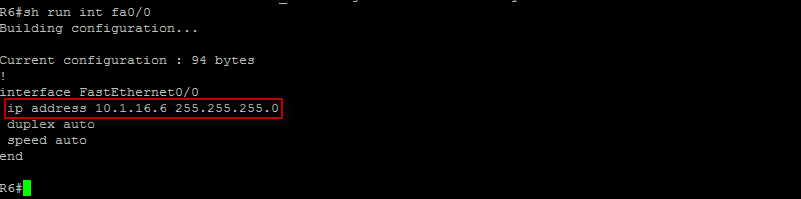
All right ! IP address is configured on the egress interface of the CE router at the HeadQuarter. Let’s move to the opposite end CE router…
Good ! Let’s take a road trip back to the PE routers and configure our Xconnect Attachment Circuit…
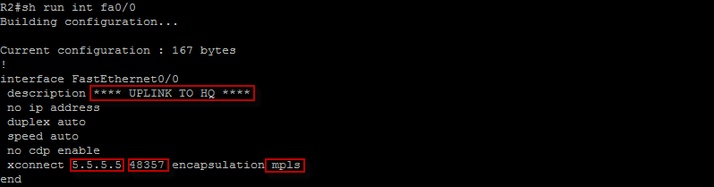
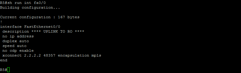
Here on the interface facing the customer, we’ve established a connection to the remote end PE router by specifying the router-ID (5.5.5.5). We’ve also specified a 32-bit unique identifier called VC ID (48357 in our case) which is shared between the PE routers. We’ve also disabled cdp protocol.
Note that the combination of the peer router ID and the VC ID must be unique on the router.
We’ve then specified the tunneling method used to encapsulate data in the pseudowire. Let’s do the same on R5…
Good ! Let’s verify that EoMPLS is up and running
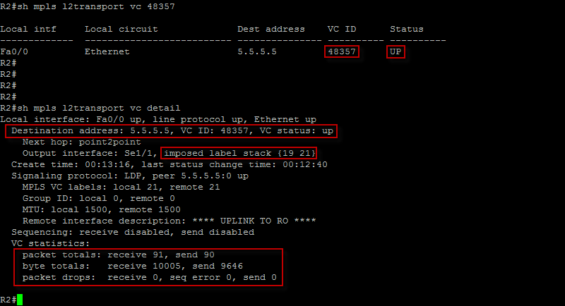
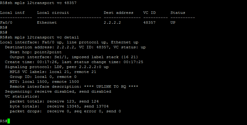
Great ! The VC status is “UP” which is always good and we can also see incremental packet flow. Let’s do the same on R5…
Good ! Let’s hop back on R1 and make sure we see R6 as “directly connected”….
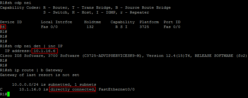
Even though we are going through the MPLS backbone, we see R6 as directly connected and from R1 perspective, both CE router share a common broadcast domain (10.1.16.0/24).
That’s what I wanted to show you. Please leave a comment if you have any questions.
 Hi, I'm Pape ! Folks call me Pop. I'm CCIE #48357. I love what I do and enjoy making tech easier to understand. I also love writing, so I’m sharing my blog with you
| M | T | W | T | F | S | S |
|---|---|---|---|---|---|---|
| 1 | 2 | 3 | 4 | |||
| 5 | 6 | 7 | 8 | 9 | 10 | 11 |
| 12 | 13 | 14 | 15 | 16 | 17 | 18 |
| 19 | 20 | 21 | 22 | 23 | 24 | 25 |
| 26 | 27 | 28 | 29 | 30 | 31 | |
Excellent explanation and example of xconnect layer 2 MPLS. I will definitely reference this to my mpls students in future class so they can come take a look
Thank you very much Paul. I really appreciate it and I do enjoy your MPLS class ! Your explanation method is the best !