
Welcome to the Network Engineering Domain
Pape O. Fall's Blog
In this post, we will look into setting up MPLS VPN and use RIPv2 as our routing protocol between the PE router and the CE router. We won’t go deeper into the MPLS VPN backbone configuration but just the PE-CE segment. At this point, if you are unfamiliar with MPLS VPN, please read this post here.
To be consistent, we will use the same MPLS diagram we’ve been using…
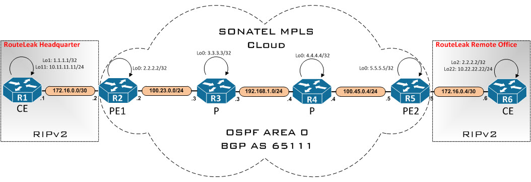
MPLS is fully configured except the links between the PEs and the CEs. Let’s hop on the consoles and configure our PE routers…
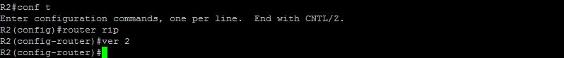
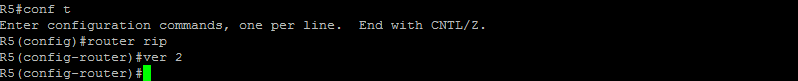
Here, we have enabled RIP version 2 on PE1. Let’s do the same on PE2…
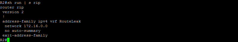
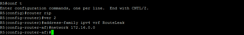
Our next step is to configure RIP routing context for VRF RouteLeak and add our directly connected networks into the VRF context. Let’s do that…
Here’s what it looks like on PE1…
Commands on PE2…
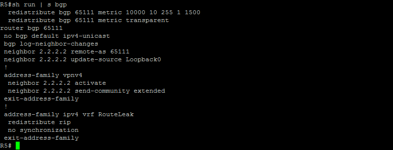
Excellent ! Our next step now is to redistribute BGP into RIP. Let’s do that…
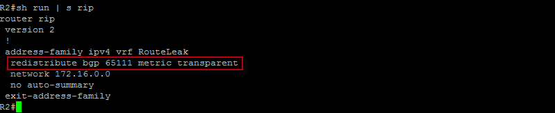
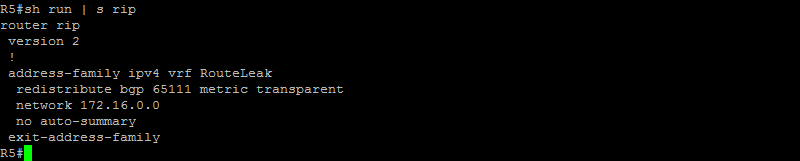
Here the keyword “Transparent” ensures that RIP metrics are sent across unmodified when advertised to MP-iBGP. Basically, the metrics are redistributed back into RIP on the other side unmodified. Let’s do the same on R5…
Very Good ! Logically… Since we have redistributed BGP into RIP, we now need to redistribute RIP into BGP. Let’s do that on PE1…
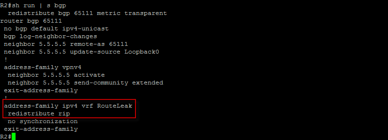
Here, we have redistributed RIP into BGP under the appropriate VRF context. Let’s do the same on PE2…
Good ! We should now be done with the PE routers… Let’s hop on the CE routers and configure RIPv2, disable auto summarization and advertise our networks into the routing protocol…
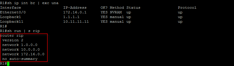
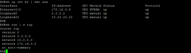
Let’s do the same on the other side…
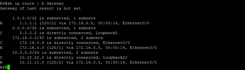
Excellent ! Let’s check the routing table on the CE router at the HeadQuarter…
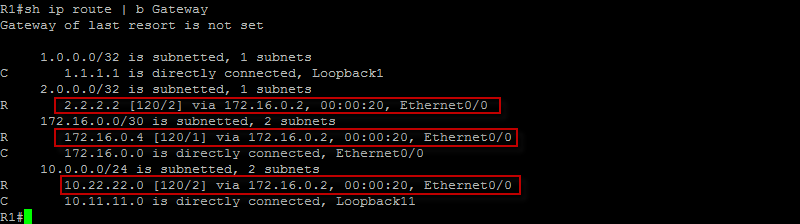
As you can see here, we are successfully seeing RIP routes installed on the main routing table. let’s check the other side…
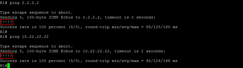
Excellent ! Let’s make sure we can successfully ping across…
Okay ! Let’s check the routing table on PE1 for VRF RouteLeak…
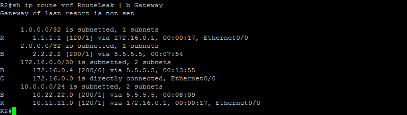
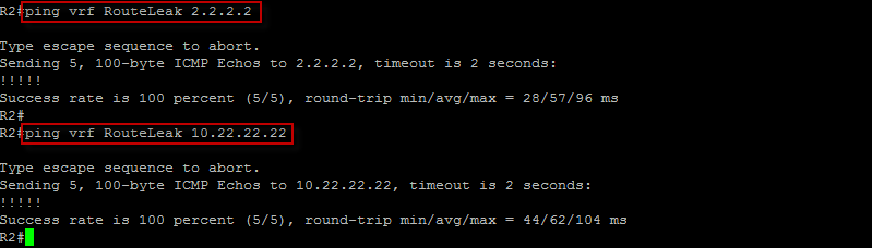
All routes are adequately installed in the routing table for VRF Routeleak. Let’s make sure we can get to the network segment on the CE router at the remote office…
Let’s now trace from the CE router at the HQ to the CE router at the RO. We should see the routers in the path including the MPLS VPN SP devices…

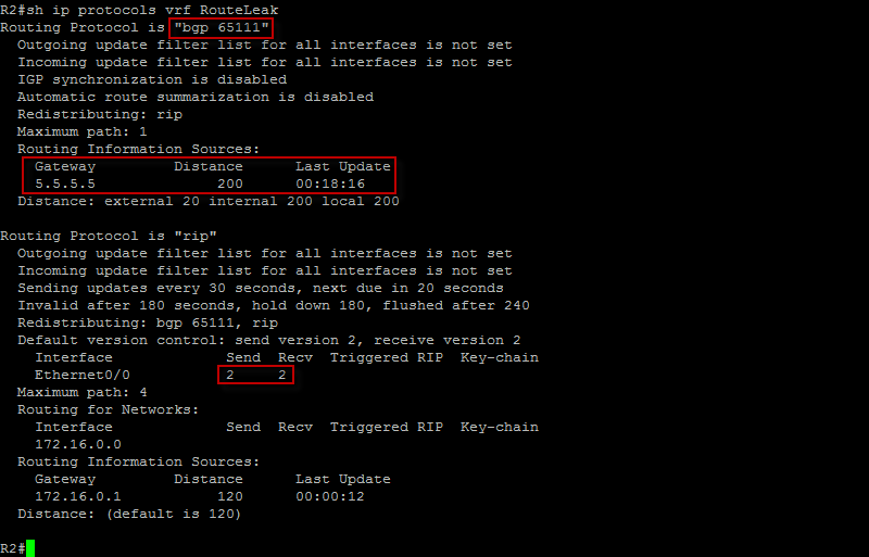
Good ! At the PE router, we can get useful information by checking the routing protocol being ran for VRF RouteLeak…
That’s the end of it. Please leave a comment if you have any questions.
 Hi, I'm Pape ! Folks call me Pop. I'm CCIE #48357. I love what I do and enjoy making tech easier to understand. I also love writing, so I’m sharing my blog with you
| M | T | W | T | F | S | S |
|---|---|---|---|---|---|---|
| 1 | 2 | 3 | 4 | |||
| 5 | 6 | 7 | 8 | 9 | 10 | 11 |
| 12 | 13 | 14 | 15 | 16 | 17 | 18 |
| 19 | 20 | 21 | 22 | 23 | 24 | 25 |
| 26 | 27 | 28 | 29 | 30 | 31 | |
Leave a Reply