
Welcome to the Network Engineering Domain
Pape O. Fall's Blog
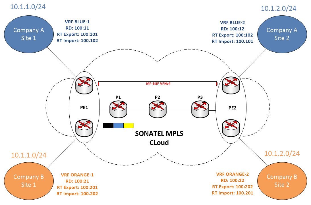
In this post, we will talk about MPLS (Multiprotocol Label Switching) which is an open standard base protocol capable of transporting different type of either L2 or L3 payloads. We will look at facts in terms of the origin of the protocol, some of the different design options we have available today and how to configure it end-to-end. For the sake of this demo, we will be using the following topology:
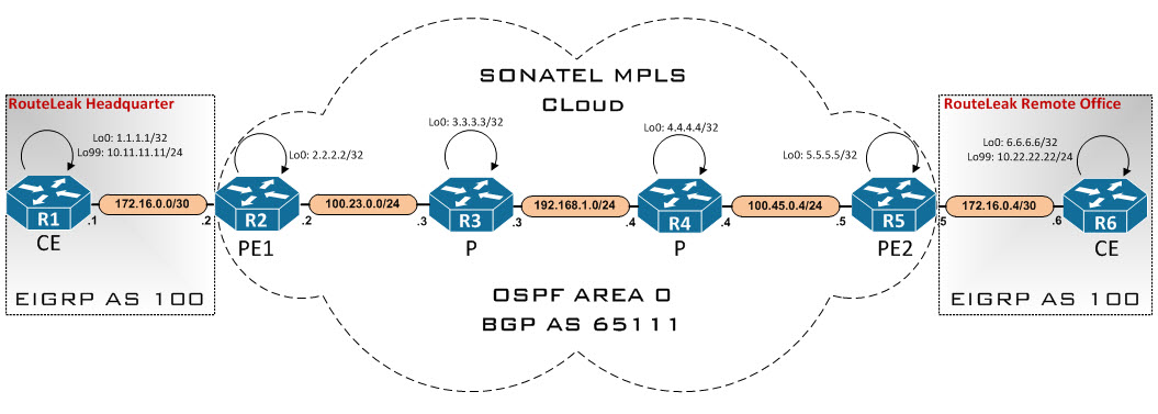
Here we have a company named RouteLeak which needs to connect to one of its remote office through the MPLS VPN backbone. The MPLS cloud is managed by a Service Provider named SONATEL.
Here are the steps we will use to configure the above design from end to end:
*Enable CEF
*Configure the MPLS VPN backbone (OSPF Area 0)
*Configure MPLS on core interfaces
*Configure LDP (Label Distribution Protocol)
*Configure LDP router-id
*Configure global BGP parameters
*Configure MP-BGP neighbor relationship
*Configure BGP update source interface the loopback 0
*Configure VRF instances (Virtual Routing and Forwarding)
*Configure VRF interfaces
*Configure PE-CE routing protocols (We can either use dynamic routing protocols or static routes)
*RouteLeak routes redistribution into MP-BGP
But first let’s talk about MPLS and its origin… In order to really understand MPLS, we need to analyze how it came about and the issues it resolves which are related to “Control Plane” and “Data Plane” problems. Let’s use a mock topology just to illustrate that…
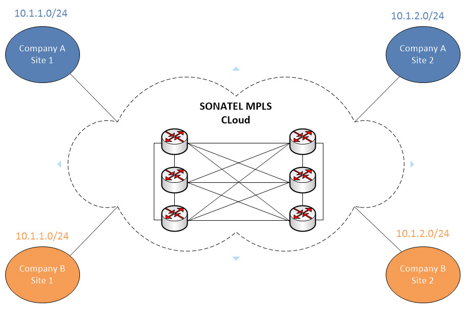
All right, so let’s say we are the Service Provide named SONATEL. We have a plain MPLS cloud composed by a couple of routers deployed in full mesh model. Two distinct potential customers as you can see in the topology above would like to use our services but the problem is that they happen to use the same IP addressing scheme (10.1.1.0/24 and 10.1.2.0/24). How do we distinguish that traffic once it arrives at SONATEL’s cloud ? How does MPLS solve the Data Plane and Forwarding Plane problem and ensures that customer traffic gets across safe and sound ?
First thing first, we need to connect to the customer’s network somehow right ? Based on different design cases, you can skin it many different ways but for the purpose of this example we will just connect the customer’s CE (Customer Edge = Last router in the customer network before connecting to ISP) router to our PE (Provider Edge = Last router managed by the ISP before connecting to customer) router via some form of direct link. Let’s add them on the diagram so we can visualize it better.

All right, so what we have done is as followed:
-We’ve minimized the full mesh topology in our cloud for simplicity and clarity purposes
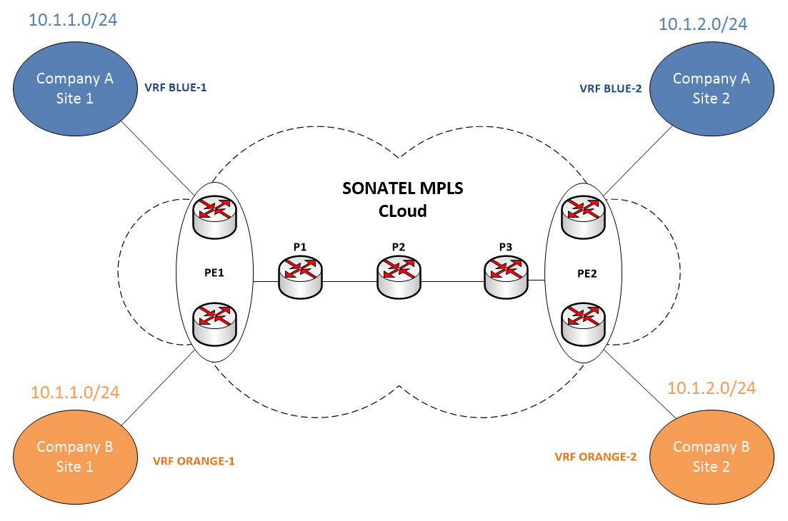
-We have also installed our PE routers and connect the customers to them. We now have now PE1 and PE2 which then connect to our Provider routers (P).
What needs to be done is basically provide a separation between Customer A and Customer B routing domain and we will leverage VRF technology to help us accomplish that. VRF stands for Virtual Routing and Forwarding and it basically allow the creation of multiple instances of routing table in a single router. It is extremely useful as it eradicates the need for several physical routers and also isolate the overlapping networks from one another. Let’s add the VRFs onto our diagram…
Ok good ! Now we have several isolated routing tables in our PE routers which are:
-Main Routing Table
-Blue Routing Table (Routing table for Customer A)
-Orange Routing Table (Routing table for Customer B)
Now let’s assume for a second that Company A (Site 1) wants to reach Company A (Site 2). PE1 receives the packet from Customer A (Site 1) and performs a lookup in the BLUE routing table as Customer A is in VRF Blue. However, the blue routing table only exist on the PE routers and not the P routers. So let’s assume again for a second that the packet somehow makes it to P1 router… I suppose you guessed what’s going to happen next since there is no “Blue Routing Table” per say on P1. The packet will be dropped once P1 check its local LFIB table !
There are many methods you can solve this without the need of MPLS but they all present huge disadvantages. You could create sub-interfaces across the P routers and map the VRFs information across the backbone… It is called VRF Lite. That way when the packet reaches PE1 and a forwarding decision is made, packets won’t be dropped as P1 now knows to forward the frame to P2…
But is this really a good design ? Imagine the burden you’ll endure if you have 1000 P routers or 1500 VRFs. That solution just does not scale and adds massive administrative overhead.
MPLS VPN solves that issue by restricting the complexity and overhead to the edges of the MPLS network (PE routers) and have a simple and scalable fast core that forwards traffic extremely fast.
Now the question is, how do we get PE1 to systematically forward the packet across the backbone without the P routers knowing about any of the complexity ?
This is where Penultimate Hop Popping comes into play. It refers to the process whereby the outermost label of an MPLS tagged packet is removed by a Label Switch Router (LSR) before the packet is passed to an adjacent Label Edge Router (LER). Now, what’s going to happen is a tag referring to the Main routing domain and a tag referring to the Blue routing domain are primarily added by PE1 and forwarded to P1. P1 then pops the outermost label, adds its own and forward it to P2 and so on…
Now you can imagine what happens when you get to the router before last which is P3 in this case ? The outermost label is popped and the packet is sent to PE2 with a single tag. That’s where we wil encounter our first problem which is the FORWARDING PLANE PROBLEM we were referring to in the beginning of this post.
PE2 receives the packet from an interface that’s in its main routing table. PE2 runs it normal routine which is checking the LFIB table to determine where to forward the traffic but 10.1.2.0/24 does not exist in the main routing table. So the packet is now dropped !
So in summary, with MPLS itself we were able to get the packet from PE1 to PE2 but the packet gets dropped at PE2 due to a Forwading Plane problem.
Now that we know about the Forwarding Plane problem, let’s talk about the Control Plane problem.
Imagine you had multiple PE routers in your network. How does PE1 knows to send the packet to PE2 and not some other PE router ? That’s the CONTROL PLANE PROBLEM.
We need to somehow get the routing information from the Customers (with the correct VRFs) and send it to the PE routers through the P routers given that we are only running MPLS in the cloud. Fortunately for us, there is a protocol we can use to send those routing information across with the appropriate VRFs so the PE routers know how to get to the destination network via any specific VRF. It is BGP ! First we need to exchange routing information between the customers and the PE routers. There are several methods you can use to accomplish that depending on what routing protocol you are using but we will come back to that. Let’s fix the Control Plane Problem first…
So you may be wondering now, how does BGP know to forward packets from Customer A (Site 1) to Customer A (Site 2) and not forward it to Customer B (Site 2) since they are in the same network. That’s where once again a new technology is introduced and it is called RD (Route Distinguisher).
RD is a 64bit identifier and its main purpose is to make the route unique by prepending its value to the route address itself. This is a study on its own. But in our case, we will use the following RD:
*Customer A (Site 1): 100:11
*Customer A (Site 2): 100:12
*Customer B (Site 1): 100:21
*Customer B (Site 2): 100:22
Here is what the address will look like once the RD is prepended to the route:
*Customer A (Site 1): 100:11:10.1.1.0/24
*Customer A (Site 2): 100:12:10.1.2.0/24
*Customer B (Site 1): 100:21:10.1.1.0/24
*Customer B (Site 2): 100:22:10.1.2.0/24
BGP will consider the extended addresses when it performs a best path selection.
We now are in good shape as those addresses are now different from one another, right ?. The RD is solely used to ensure VPN routes are unique.
But hold on… We have just created additional issues by fixing the above problem.
Problem 1 – The extended routes are no longer IPv4 routes ! IPv4 routes as you may know already are 32bit long and what we have now are 96bit long addresses. The question now is can BGP carry 96bit long routes ? The answer is NO it can not ! This is where we introduce once again a new technology called MP-BGP (Multi Protocol BGP) and more specifically, the VPNv4 address family.
The VPNv4 address family allows us to carry 96bit prefixes which are composed by the RD and the IPv4 routes.
Problem 2 – Once the 96bit address arrives at the PE router, how do we tie it with the customer network ? We now have the capability to get the route across from PE to PE but how do we associate the blue route for instance to Customer A. You would tell me that we can use the RD as specified above but it turns out that it presents some limitations because its role is to only ensure VPN routes are unique. For that purpose, we will again introduce a new technology to help just do that. They are extended BGP communities called RT (Route Target).
The RT are assigned to the routes as they are being injected to the MP-BGP. These are configured under respective VRF and route lookup is then performed based on the VRF routing instances. Let’s now choose our RT (It is also an Admin decision).
*Customer A (Site 1): 100:11:10.1.1.0/24
*RT: 100:101
*Customer A (Site 2): 100:12:10.1.2.0/24
*RT: 100:102
*Customer B (Site 1): 100:21:10.1.1.0/24
*RT: 100:201
*Customer B (Site 2): 100:22:10.1.2.0/24
*RT: 100:202
Note that you can use the same RT between Customer A sites or between Customer B sites. Let’s see what we’ve described in the topology…
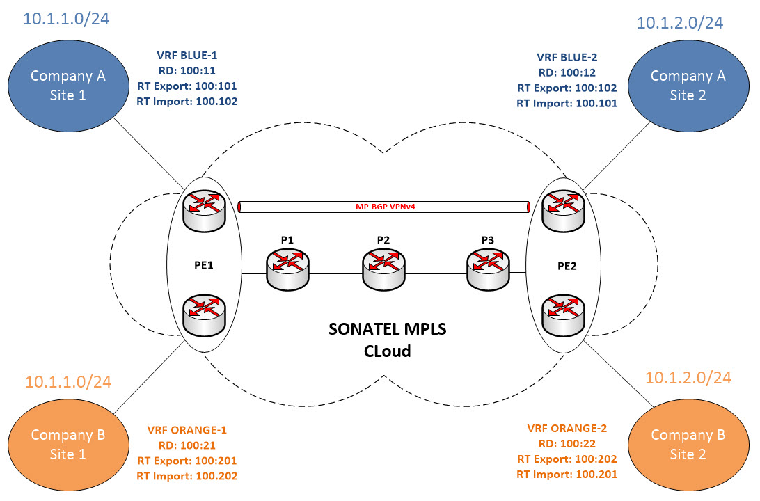
So at this point, the PE routers will ensure that only routes that have certain RT will be placed in their respective VRF. The “import” and “export” keywords determine respectively which routes to import and under what RT and VRF and which routes to export.
In summary, we have now solved the problem of getting the routes across by leveraging MP-BGP. We have also solved the problem of distinguishing the routes between multiple VRFs and we have also solved the problem of sorting these routes into distinct routing tables. Grosso Modo, we have solved the CONTROL PLANE PROBLEM.
Let’s go back a bit and solve the Forwarding plane problem…
Remember the PHP process where the PE router does not know where to forward the packet ? Let’s look at our diagram again but this time we will include the Labels…
So in recap, the forwarding plane problem we were experiencing was due to the PHP process which consisted of the router popping the black label and we ended up with only the Blue label once we reached PE2. To solve the problem, we inject an extra label into the packet that will instruct the PE router to forward the packet to the appropriate destination via the adequate VRF.
From Customer A perspective, let’s say the yellow label is the orignal packet and the blue label is the extra label we’ve just talked about. It is called the VPN Label.
When the yellow packet arrives at PE1, a blue label (VPN Label) and a black label (Transport Label) are imposed onto the frame. The black label (Transport Label) will be used by the P routers within our backbone to get the packet across to PE2. So P1 swaps the black label and forward it to P2 and so on… P3 performs an “Implicit Null” operation meaning it pops the Black Label (Transport Label) and forward the packet to PE2. Now with the help of the Control Plane, PE2 now knows where to send the packet because the VPN information has been exchanged between the PE routers with the use of MP-BGP at the Control Plane level. Note also that MP-BGP carries the routes, the RD, the RT and also the label information.
Well, we have now solved the Control Plane and the Forwarding Plane problems ! Let’s now dive into the consoles and build our MPLS VPN network using the 1st topology in this post…
All IP addresses are pre-configured. Let’s start by building our MPLS VPN Backbone – We will be using OSPF as the IGP in our case…
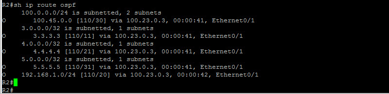
As we can see here, our unicast routing seems to be good now. We have OSPF routes between the P routers. This is very important as we will use the loopback addresses to build the LDP sessions. If your routing does not work, MPLS will most likely not work as well. Our next step is to configure IP CEF and enable LDP on all the interfaces. Let’s do that…
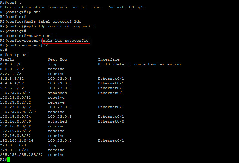
We’ve just enabled IP CEF and LDP on all the P routers. Typically, you would enter the command “mpls ip” on all interfaces except the ones facing the customer but since we are running OSPF, the command “mpls ldp autoconfig” does the work for us. It dynamically enables LDP on all interfaces running OSPF. Also by default, the label protocol is actually “LDP” but it is always good practice to punch in the configuration as you know it just to make sure nothing is missed. Let’s see if we have any LDP neighbor relationship…
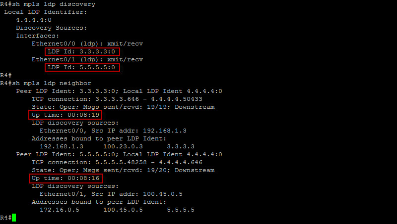
Looks like we are solid here ! I’ve ran the same commands on R2, R3 and R5 just to make sure. So here is what happened in the background – The very moment LDP was enabled on the interfaces, it multicasted a discovery UDP packet with the local LDP router-ID. The LDP sessions were then built using the router-ID and the LDP neighbors exchanged prefixes as well as label bindings which populated the LFIB table. Let’s now check the LFIB table on R2 for instance…
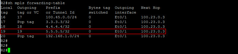
So now R2 has learned these prefixes and label bindings from its peers. If you look at the loopback IP address of R5 which is 5.5.5.5/32 – If R2 receives a frame with R5 loopback as the destination IP, it will systematically inject a MPLS label with a value of 19 between the L2 frame and the IP header. It will then change the L2 PID (Protocol Identifier) value in the L2 frame header to indicate that the next protocol is MPLS and not IP.
Now we can move on to the next step but let’s fine tune our configuration a bit. In our case here, we only need labels for the loopback addresses which we will also use to build our MP-BGP session between the PE routers. So let’s ensure the routers generate ONLY labels for the loopbacks. We will configure the following on all of the P routers…
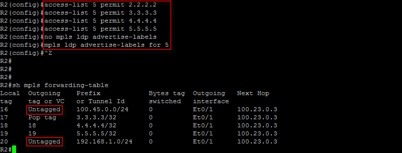
All right ! We are good to go ! As you can see, we only have labels for the loopback addresses now. Our next step is to configure MP-BGP between our PE routers. Let’s do that…
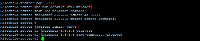
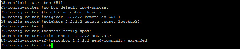
The “no bgp default ipv4-unicast” command prevents BGP to dynamically establish a session once the neighbors are defined. The “neighbor x.x.x.x activate” is then needed under the appropriate address family for the session to come up. As you can see here, we entered the VPNv4 address family to specify our neighbor. Let’s do the same with R5…
Let’s now check our MP-iBGP session from R2 perspective…
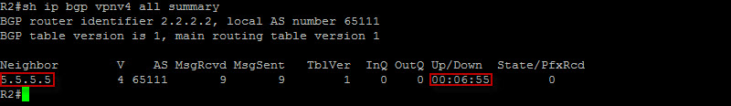
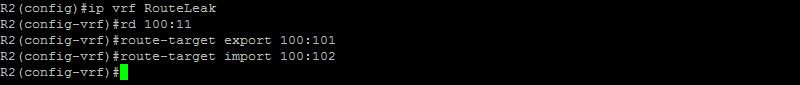
Perfect ! We are almost there ! Let’s now configure the respective VRF instances per our diagram on the PE routers…
Great ! Let’s do the same with R5…
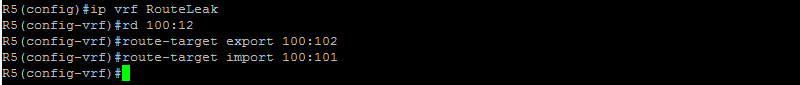
Have you noticed how the RT imported on one side needs to be exported at the opposite side ? Now we need to associate the VRF with the corresponding CE interface…
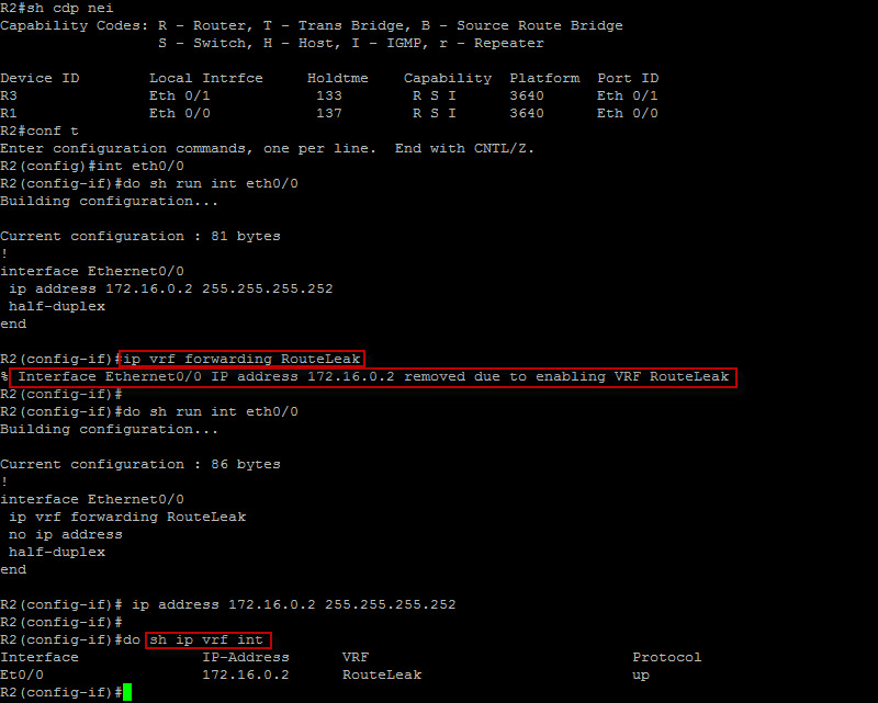
We now have the interface placed in the correct VRF. I wanted to show you how the ip address is removed by default when the command “ip vrf forwarding RouteLeak” is entered. You will need to reconfigure the IP address on Ethernet0/0. We will do the same on R5 and move on to our next step which is to establish some form of dynamic routing between the PE routers and the CE routers. We could also use static routes but for the sake of this demo, we will leverage EIGRP. Let’s build the routing context for EIGRP now…
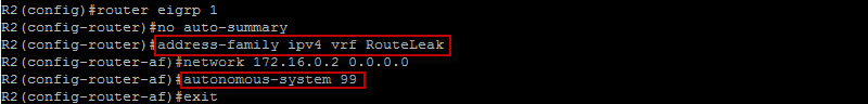
Notice how we specified the network under the address family with the correct vrf ? Also, the command “autonomous-system 99” basically allow the peering with a remote router running EIGRP AS 99. In our case, R1 and R6 are running EIGRP AS 99. Let’s configure R1 with EIGRP and make sure we have adjacency…
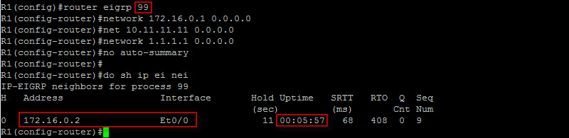
This looks very good ! Let’s do the same between R5 and R6 and check the routing table on R5…
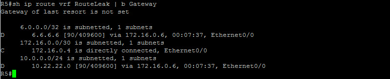
Nice ! If we run the same command on R2, we would also see R1 routes. Let’s now move onto our next step which is performing mutual redistribution at the PE level. The reason for this step is to propagate the CE routes across our backbone and vice versa. This process will allow VPNv4 prefixes to be exchanged between PEs. Let’s start with R2…
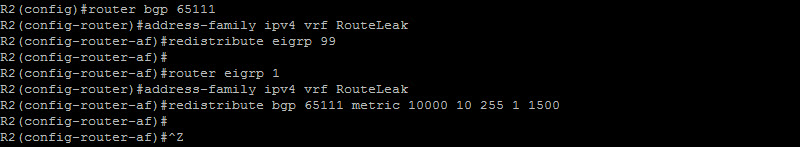
Very nice ! I have configured the same on R5. Note that this is not necessarily a design I would suggest, RouteLeak is redistributing its entire routing table to the ISP. There are other methods we could use so the ISP will not see any of our routes and one of them is via GRE tunnels. We will see that in a different post. Now let’s check to make sure if we have in fact received VPNv4 prefixes at our PE routers…

This is fantastic ! We can clearly see that R2 is receiving the VPNv4 prefixes. Let’s check R5…
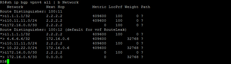
Awesome ! We are solid here as well ! At this point, we should be able to ping from R1 to R6…
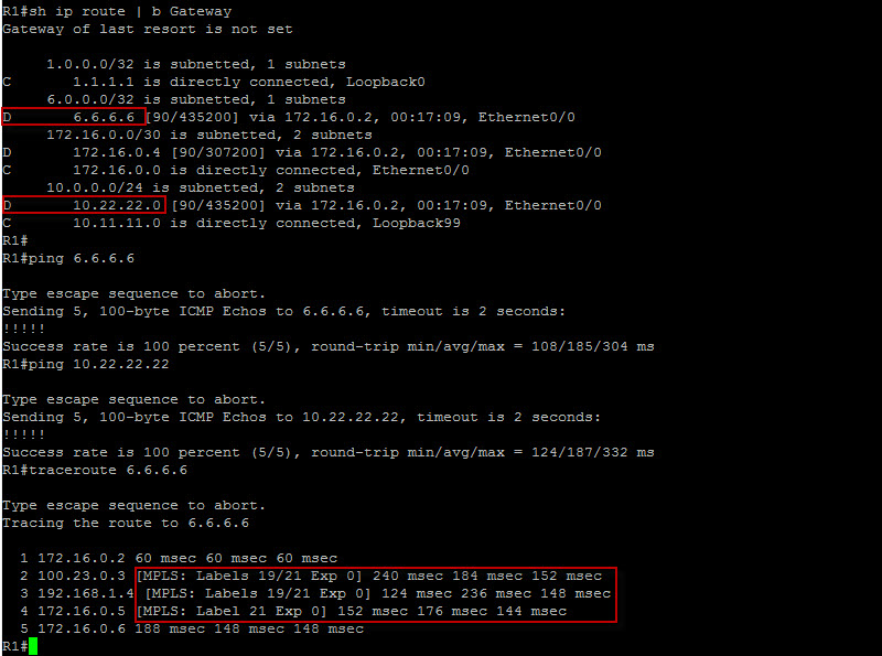
Well, our endgame is now fulfilled. We can clealy see the MPLS labels with the traceroute output and we can also successfully reach the RouteLeak remote office prefixes from the headquarters through the MPLS VPN backbone.
The following is the GNS3 file pertaining to this lab – You can download it here.
Quick Tips: Route Target is for the control plane and the VPN label is for the Data Plane.
That completes this topic… I’ll talk to you guys later.
 Hi, I'm Pape ! Folks call me Pop. I'm CCIE #48357. I love what I do and enjoy making tech easier to understand. I also love writing, so I’m sharing my blog with you
| M | T | W | T | F | S | S |
|---|---|---|---|---|---|---|
| 1 | 2 | 3 | 4 | |||
| 5 | 6 | 7 | 8 | 9 | 10 | 11 |
| 12 | 13 | 14 | 15 | 16 | 17 | 18 |
| 19 | 20 | 21 | 22 | 23 | 24 | 25 |
| 26 | 27 | 28 | 29 | 30 | 31 | |
Hello, its good article. It is a wonderful source
of information.
Hello Brother, I appreciate your effort. Really very nice post.
100 likes
Hi Sameer ! Thank you for the encouraging words ! I’ve also received your voicemail. Thanks again 🙂
Good day! I just want to give you a huge thumbs up for the great info you
have here on this post. I will be returning to your website
for more soon.
We absolutely love your blog and find almost all of your post’s to be just
what I’m looking for. Does one offer guest writers to write content in your case?
I wouldn’t mind publishing a post or elaborating on a
few of the subjects you write concerning here.
Again, awesome blog!
Thank you buddy ! I have not opened it to public yet but you brought a good point. I’ll definitely think about it 😉
Awesome ! Looking forward to have you back 🙂
Fine way of explaining, and nice piece of writing to take information concerning
my presentation subject, which i am going to present in school.
Glad this post helps with your presentation ! Good Luck !
Can I simply just say what a comfort to discover an individual who really understands what they’re discussing over the internet.
You certainly know how to bring a problem to light and make it important.
More and more people must check this out and understand this.
I was surprised that you are not more popular given that you
definitely have the gift
Glad to see your comment 🙂
Great article.
Thank you !