
Welcome to the Network Engineering Domain
Pape O. Fall's Blog
Both Network Address Translation (NAT) and Port Address Translation (PAT) perform similar functions with regards to remapping RFC 1918 IP address(es) to IP address(es) on an external network segment.
With the proliferation of IoT and the rapid extension of IPv4 addresses, this technology has become essential with regards to conserving Private IP address Pool. In order to understand NAT & PAT, it is imperative to understand the problems it resolve and the underline functionality in the back end.
Nowadays, many hosts within an organization do not need access to the internet such as machines and server within a Scada Network for instance (In most cases). Hence, there is no need for a globally unique and routable IP address for the latter. IPv4 exhaustion led to the creation of Private IP addressing schemes which are defined in RFC 1918; These non-overlapping network segments are NOT routable on the internet and do not need to be registered with IANA. These addresses are to be freely use on a LAN segment with proper IP address allocation design.
RFC 1918 address ranges are:
10.0.0.0/8 (10.0.0.0 – 10.255.255.255)
172.16.0.0/12 (172.16.0.0 – 172.31.255.255)
192.168.0.0/16 (192.168.0.0 – 192.168.255.255)
NAT & PAT then come into play to translate the above addresses into routable IP address(es) for outside communication purposes. There are different methods to configure NAT but first let’s run through the terminology you will need to know in order to grasp the concept.
Inside Local—This is the private IP address of machine sitting on a Local Area network (e.g., a workstation’s IP address).
Inside Global—This is the public IP address that translate the private IP address. Outside network sees this IP address as your local host’s.
Outside Local—This is the local IP address from the private network, which your local host sees as the IP address of the remote host.
Outside Global—This is the public IP address of the remote host (e.g., the IP address of the remote Web server that a workstation is connecting to).
Let’s illustrate the above with a diagram…

Here is a brief overview of what takes place in the back-end when Host A sends a request to the Web Server:
The above example is called Static NAT because there is a 1:1 correlation between the private IP address and the public IP address.
It is important to note that the entire NAT process is locally significant to the router performing the translation. Hence, both internal and external network are clueless of the remapping functions.
PAT on the other hand (One-to-many NAT), is often referred as “NAT Overload”. This is the most typical translation configuration you would see as it systematically reduces the waste of public IP addresses. Most companies uses Static NAT to translate Inside Local addresses of servers needing to be accessed from the outside. Users traffic are typically translated using PAT at the edge router which allows the use of a common Global IP address for numerous Private IP addresses.
Let’s illustrate it with a diagram…
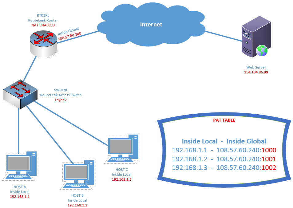
This what happens here:
That’s all I wanted to share today. There are different design methods pertaining to NAT/PAT which we will see in different posts.
 Hi, I'm Pape ! Folks call me Pop. I'm CCIE #48357. I love what I do and enjoy making tech easier to understand. I also love writing, so I’m sharing my blog with you
| M | T | W | T | F | S | S |
|---|---|---|---|---|---|---|
| 1 | 2 | 3 | 4 | 5 | 6 | |
| 7 | 8 | 9 | 10 | 11 | 12 | 13 |
| 14 | 15 | 16 | 17 | 18 | 19 | 20 |
| 21 | 22 | 23 | 24 | 25 | 26 | 27 |
| 28 | 29 | 30 | ||||
Thank you Mr Pop for sharing all this knowledge. Your blog is very ressourcefull. I hope with the time we can get some videos very soon
Hi Pis 🙂 I haven’t been writing like I used to due to time constraint. However, I’m planning on making the videos very soon.
Nice Post ! It’s always a pleasure to read you. J’apprécie la clarté des postes et l’agencement des explications qui facilitent a lot la compréhension.
But i am still waitin a post on COS, Multicast .
See you soon
What’s up buddy ! Yeah, j’etais tres occupe ces temps ci mais je vais m’y mettre tres bientot.
Stay tuned 😉