Welcome to the Network Engineering Domain
Pape O. Fall's Blog

Optimizing VXLAN with vPC Fabric Peering

vPC Fabric Peering is a critical technique in VXLAN BGP EVPN environments for achieving seamless Layer 2 connectivity and Anycast Gateway functionality while maintaining control-plane and data-plane consistency. This blog post walks through the motivation behind vPC Fabric Peering, its architecture, and why it enables resilient and scalable data center fabric operations.

Let me guide you through what this technology means and why it is essential in some corner cases. Imagine two leaf switches working as one virtual unit to deliver high availability and load balancing for servers or endpoints. Now imagine they also need to route VXLAN-encapsulated traffic across a data center fabric. That’s where vPC Fabric Peering becomes not just useful but essential.

At its core, vPC (Virtual Port-Channel) allows two Nexus switches to appear as a single logical switch to a downstream device (like Server X in our diagram below). This avoids STP blocking and supports multi-chassis link aggregation (LAG) via 802.3ad. However, when integrated with VXLAN and BGP EVPN, traditional vPC alone doesn’t cover the entire picture, especially for routing VXLAN traffic between leaf switches.

In a VXLAN/EVPN fabric, you can deploy leaf switches in a traditional vPC topology using physical peer-link and keepalive interfaces, or you can adopt vPC Fabric Peering, which is a more modern approach designed specifically for VXLAN environments. Both enable active-active connectivity and redundancy, but they differ in scalability, control-plane behavior, and compatibility with VXLAN overlays.

Option 1: Traditional vPC (Peer-Link + Keepalive)
This is the classic method displayed in the diagram below where:

  • A separate vPC keepalive link (L3 or mgmt) ensures health monitoring.
  • Two leaf switches are connected via a dedicated vPC peer-link (Layer 2 trunk).
  • Both switches independently participate in VXLAN as VTEPs.

This setup works in traditional L2 networks and can be used with VXLAN, but introduces challenges in overlay networks due to Layer 2 peer-link semantics.

Option 2: vPC Fabric Peering (vFP)
In this approach as displayed in the diagram below:

  • This link allows for VXLAN encapsulated traffic to be exchanged directly between vPC peers.
  • The peer-link is replaced by a Layer 3 routed point-to-point link between the vPC VTEPs (Typically the NVE Source Loopback IP)
  • No traditional trunk or spanning-tree dependency.

This design is optimized for VXLAN overlays and removes the reliance on classical L2 bridging between the leaf switches.

Let’s break down the vPC Fabric Peering (vFP) configuration between LEAF01 and LEAF02 in a Cisco Nexus VXLAN EVPN fabric

Since this is a VXLAN Fabric, the foundational services must be enabled on the switches as follow:

feature nv overlay
feature vn-segment-vlan-based
feature interface-vlan
feature ospf
feature pim
feature bgp
feature vpc

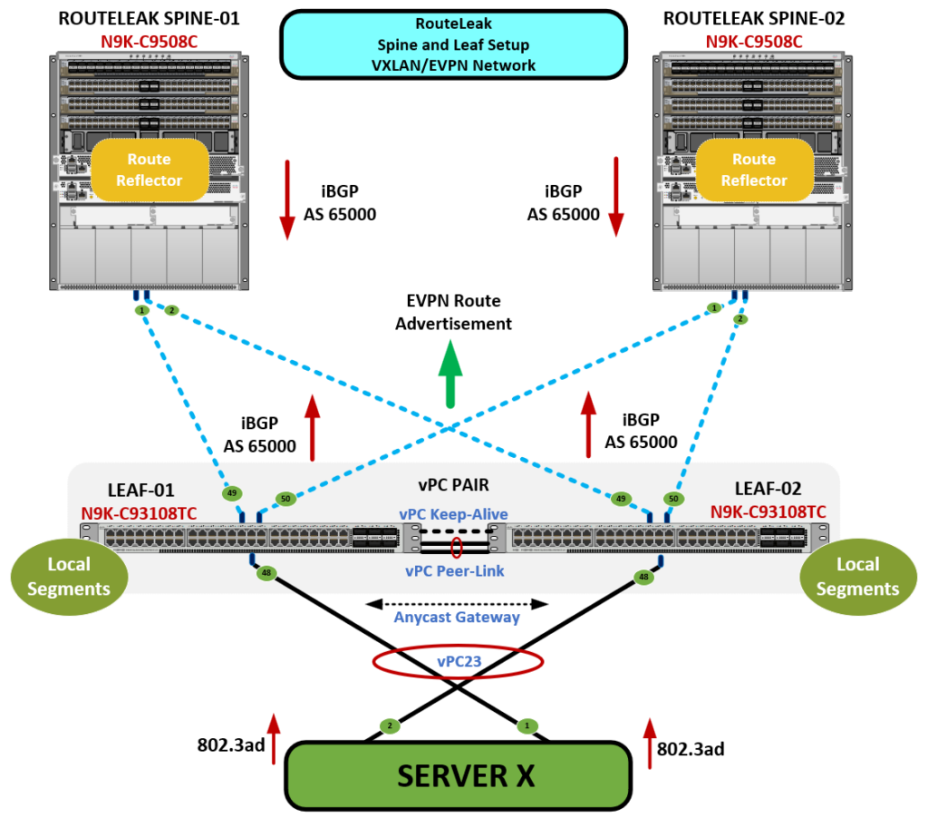
One thing to keep in mind here which is different from setting up traditional vPC is that, in a VXLAN EVPN fabric with vPC Fabric Peering, you must allocate TCAM resources to the ing-flow-redirect region with a minimum value of 512 so the switch can handle traffic redirection between vPC peers. This enables hardware-based flow processing required for functions like virtual peer-linking, Anycast Gateway support, and VXLAN encapsulated traffic forwarding between vPC members.

Without TCAM allocation, features like peer-gateway, ARP/GARP replication, and ingress redirection will not function, leading to blackholing or asymmetric traffic behavior.


Now let me give a low level explanation of TCAM and why we need it in this context:

Imagine two best friends (switches) working together to serve you candy (data). They promise to always share, but they need a special notebook to remember who took what and when. If they don’t have that notebook, they can forget your order, or worse, both try to deliver it and cause chaos.

In your switches, that “notebook” is TCAM (Ternary Content-Addressable Memory). A super-fast memory used to match complex rules like:

“If this VXLAN packet comes in and it’s for this MAC, then forward it through that peer.”

Now, when you use vPC Fabric Peering, you’re saying:

“Dear switch, instead of a physical link, please remember how to forward traffic to your peer using VXLAN tunnels.”

To do this, the switch needs pre-allocated memory space (TCAM region) to install and match redirection rules.


Now let’s talk about why we really need TCAM at a more advanced level:

✅ 1. vPC Virtual Peer-Link over VXLAN Needs Redirection

  • In traditional vPC, the peer-link is a Layer 2 trunk and traffic redirection is implicit via bridging.
  • In vPC Fabric Peering, the “peer-link” is virtualized over VXLAN tunnels using NVE interfaces.
  • This redirection is done via Ingress Flow Redirection, which needs hardware TCAM entries to match VXLAN traffic that must be sent to the vPC peer.

✅ 2. ARP/GARP/DHCP Flood Handling

  • ARP and DHCP requests from a dual-homed host must be replicated and delivered consistently to both leafs.
  • If a vPC peer receives an ARP request but doesn’t have the MAC/IP mapping, it must redirect it to its peer.
  • That redirection behavior is handled via flow redirection entries in the TCAM.

✅ 3. Anycast Gateway Peer-Gateway Function

  • The Anycast SVI IP/MAC is shared between the vPC peers.
  • When Host-A sends a packet to the gateway MAC, the switch might not own the original entry but must process or forward it on behalf of its peer.
  • That operation again uses redirect entries to the remote peer VTEP, requiring TCAM usage.

✅ 4. EVPN MAC/IP Learning Optimization

  • In a VXLAN EVPN setup, each switch learns local MACs and advertises them over BGP EVPN.
  • To ensure deterministic and symmetric traffic flows—especially in asymmetric IR models—the hardware needs to process the MAC/IP bindings against encapsulated VXLAN headers.

These complex match-actions are stored in TCAM.

Let me show you how to get it configured. First we need to check the TCAM resource allocation on the switch to verify whether ing-flow-redirect has been carved and how much space is allocated by running the below command.

LEAF-101# show hardware access-list tcam region
                                    NAT ACL[nat] size = 0
                        Ingress PACL [ing-ifacl] size = 0
                                     VACL [vacl] size = 0
                            Ingress RACL [ing-racl] size = 2304
                     Ingress L2 QOS [ing-l2-qos] size = 256
           Ingress L3/VLAN QOS [ing-l3-vlan-qos] size = 512
                           Ingress SUP [ing-sup] size = 512
     Ingress L2 SPAN filter [ing-l2-span-filter] size = 256
     Ingress L3 SPAN filter [ing-l3-span-filter] size = 256
                       Ingress FSTAT [ing-fstat] size = 0
                                     span [span] size = 512
                          Egress RACL [egr-racl] size = 1792
                            Egress SUP [egr-sup] size = 256
                 Ingress Redirect [ing-redirect] size = 0
                      Egress L2 QOS [egr-l2-qos] size = 0
            Egress L3/VLAN QOS [egr-l3-vlan-qos] size = 0
         Ingress Netflow/Analytics [ing-netflow] size = 512
                           Ingress NBM [ing-nbm] size = 0
                            TCP NAT ACL[tcp-nat] size = 0
              Egress sup control plane[egr-copp] size = 0
             Ingress Flow Redirect [ing-flow-redirect] size = 0
    Ingress PACL IPv4 Lite [ing-ifacl-ipv4-lite] size = 0
    Ingress PACL IPv6 Lite [ing-ifacl-ipv6-lite] size = 0
                        MCAST NAT ACL[mcast-nat] size = 0
                         Ingress DACL [ing-dacl] size = 0
         Ingress PACL Super Bridge [ing-pacl-sb] size = 0
       Ingress Storm Control [ing-storm-control] size = 0
             Ingress VACL redirect [ing-vacl-nh] size = 0
                         Egress PACL [egr-ifacl] size = 0
                    Egress Netflow [egr-netflow] size = 0

Here we can clearly se above that there aren’t any resources assigned to the region of interest and you cannot carve TCAM for ing-flow-redirect unless there’s enough available space. And since TCAM is finite, you often need to borrow from other regions, most commonly ing-racl. This reallocation is done by reducing the size of ing-racl, then assigning the freed-up space to ing-flow-redirect. Cisco documentation will tell you that these changes require a switch reload to take effect but I’ve observed that no reboot is needed for the resources to be properly mapped. However, my recommendation is to reboot if you do have the window.

configure terminal
hardware access-list tcam region ing-racl 512
hardware access-list tcam region ing-flow-redirect 512

First command shrinks ing-racl from its default down to 512 entries. Second command allocates 512 entries to ing-flow-redirect.

The next step here is to configure QoS on spine switches to ensure control-plane traffic, especially Cisco Fabric Services (CFS), BGP EVPN updates, ARP/GARP, and VXLAN fabric signaling—is prioritized over other traffic. This is crucial in high-throughput environments where spines are carrying massive amounts of East-West and North-South traffic, and control traffic must never be dropped or delayed.

class-map type qos match-all CFS
match dscp 56

policy-map type qos CFS
class CFS
set qos-group 7

This configuration marks packets with DSCP 56 (CS7), then classifies them into a high-priority internal forwarding class (qos-group 7).

DSCP 56 corresponds to Class Selector 7 (CS7), a reserved high-priority level. It’s used by Cisco Fabric Services (CFS). A messaging layer that underpins:

✅vPC state sync
✅vPC Fabric Peering control packets
✅MAC/IP route resolution
✅ARP synchronization
✅BGP/EVPN messages (in some designs)

Spines in a Clos topology are central transit nodes for all traffic in the fabric. They route and switch between leafs, carry VXLAN encapsulated packets, and serve as Route Reflectors for EVPN.

If CFS or control-plane traffic is queued behind data-plane traffic, or worse—dropped—you get:

  • vPC peer inconsistencies
  • Delayed MAC/IP learning
  • Broken EVPN sessions
  • Blackholes or asymmetric traffic

Prioritizing DSCP 56 ensures control messages by bypassing congestion, get low-latency treatment and remain reliable, even under heavy traffic load.

Here is the breakdown of the configuration:

class-map type qos match-all CFS
match dscp 56

!Matches all incoming packets marked with DSCP 56.
policy-map type qos CFS
class CFS
set qos-group 7

!Re-maps those packets internally to QoS group 7, which is typically reserved for high-priority traffic queues on Cisco ASICs.
interface Ethernet1/1 - 2
service-policy type qos input CFS

!This applies the QoS policy to the ingress traffic on spine interfaces.

Control-plane traffic is the nervous system of your fabric. On high-performance spine switches, QoS ensures that vital control traffic gets through regardless of bandwidth contention. This is especially important for:

✅vPC Fabric Peering stability
✅EVPN/BGP route convergence
✅Anycast Gateway consistency
✅Redundancy and failover behavior

Now the next step is to configure the vPC and here is how:

The vPC configuration in a VXLAN EVPN fabric allows two leaf switches to appear as one logical switch to downstream devices (e.g., servers, firewalls). When combined with vPC Fabric Peering, it ensures consistent forwarding, MAC learning, and Anycast Gateway operation. Even without a physical peer-link !!!

vpc domain 23
  peer-keepalive destination 1.1.1.2 source 1.1.1.1 vrf management
  virtual peer-link destination 192.168.0.2 source 192.168.0.1
  peer-switch
  peer-gateway
  ip arp synchronize
  ipv6 nd synchronize
  auto-recovery
Command Purpose
vpc domain 23 Defines the vPC domain ID shared between both switches
peer-keepalive Health monitoring to detect split-brain (over mgmt VRF)
virtual peer-link Establishes the peer-link over VXLAN (Loopback0-to-Loopback0)
peer-switch Both switches act as STP root (required for server edge ports)
peer-gateway Ensures each switch can forward traffic sent to the Anycast Gateway MAC/IP
ip arp synchronize Synchronizes ARP tables between peers to avoid resolution delay
ipv6 nd synchronize Same as above, but for IPv6 Neighbor Discovery
auto-recovery Allows vPC to recover if one peer reloads without rebooting both

In the above vPC configuration, the vPC peer-keepalive link is a control-plane heartbeat mechanism that detects if the vPC peer is alive. It’s typically terminated on the out-of-band (OOB) management interfaces.

The vPC peer-link (in traditional vPC) or virtual peer-link (in vPC Fabric Peering) carries data-plane traffic and synchronization control-plane messages like MAC/ARP sync. In VXLAN environments, this is implemented via Loopback interfaces and VXLAN tunnels, not physical trunks. In this example, 192.168.0.1 and 192.168.0.2 are the Loopback0 IPs of LEAF01 and LEAF02 respectively and these are the same IPs used for VXLAN tunnel endpoints (VTEPs).

✅ Traditional Peer-Link (Legacy vPC):
Physical trunk ports between the vPC switches carry:

  • MAC/ARP sync
  • STP BPDU traffic
  • L2 flooded traffic
  • Non-local vPC traffic
  • Must be high-bandwidth and non-routed

✅ Virtual Peer-Link (vPC Fabric Peering in VXLAN):
Is a VXLAN tunnel between the vPC peers:

  • Built over Loopback interfaces used as VTEPs
  • Replaces the physical peer-link by tunneling traffic through the VXLAN overlay

Here is the peer-link configuration. Again, it is important to remember that the configuration is in place even though there isn’t any physical links.

interface port-channel23
switchport
switchport mode trunk
spanning-tree port type network
vpc peer-link
no shutdown

The last step is to configure Port-Channel and vPC towards Downstream Device. Let’s say the downstream server is dual-homed on Eth1/48 on each switch.

LEAF101
interface Ethernet1/48
channel-group 48 mode active

interface port-channel48
switchport
switchport mode trunk
vpc 48
LEAF102
interface Ethernet1/48
channel-group 48 mode active

interface port-channel48
switchport
switchport mode trunk
vpc 48

vPC Fabric Peering is a modern, robust evolution of traditional vPC—purpose-built to align with VXLAN and EVPN fabric designs. By virtualizing the peer-link over VXLAN tunnels and offloading peer communication to loopback-based overlay paths, this model removes legacy L2 dependencies, simplifies spanning-tree operations, and enhances the scalability and resiliency of your data center fabric.

In this guide, we’ve:
✅Distinguished between peer-keepalive and virtual peer-link
✅Explained the necessity of TCAM resource allocation for VXLAN redirection
✅Covered QoS marking and prioritization to protect control-plane traffic in the fabric core
✅Detailed the complete vPC configuration with best practices and real-world deployment logic

When implemented correctly, vPC Fabric Peering ensures:
✅Consistent Anycast Gateway behavior
✅Seamless traffic failover and forwarding symmetry
✅Hardware-accelerated VXLAN packet redirection
✅Operational predictability and high availability for dual-homed endpoints

As network architectures continue evolving toward intent-based, highly virtualized fabrics, mastering vPC Fabric Peering becomes not just beneficial but essential. It empowers you to build next-generation data centers that are scalable, resilient, and fabric-aware by design.

I’ll see you on the next one !

A Little About Myself

Hi, I'm Pape ! Folks call me Pop. I'm CCIE #48357. I love what I do and enjoy making tech easier to understand. I also love writing, so I’m sharing my blog with you

Sign up to receive notifications and updates whenever new topics or videos are uploaded!

RouteLeak Calendar

April 2025
M T W T F S S
 123456
78910111213
14151617181920
21222324252627
282930