Welcome to the Network Engineering Domain
Pape O. Fall's Blog

vPC – Virtual PortChannel Explained

The goal of this post is to dive deep into vPC (Virtual Port Channel) which is a Cisco Nexus technology that allows links that are physically connected to two different switches to appear as a single logical Port-Channel to a downstream device. This eliminates Spanning Tree Protocol (STP) blocking, provides active-active link utilization, and offers link and device-level redundancy.

It is important to note here that vPC is commonly used in data center environments where servers, firewalls, load balancers, or other switches are dual-homed to two Nexus switches for high availability. With vPC, you achieve Layer 2 multipathing without loops, enhanced throughput, and faster convergence.

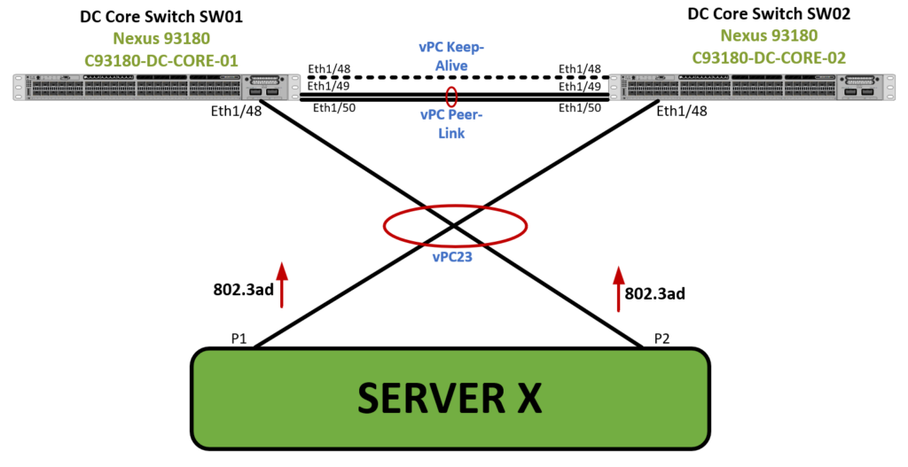
As displayed in the diagram above, Server X is connected to two Cisco Nexus 93180 switches via 802.3ad (LACP), making it a perfect candidate for a vPC deployment. This design ensures that both links are forwarding simultaneously and the server is protected against any single switch failure.

Let me give you an overview of what the vPC stanza looks like and clarification with regards to each of the commands below. Then I’ll walk you through the configuration steps. Here is what a typical vPC stanza looks like and what each commands mean:

vpc domain 100
peer-switch
role priority 1000
system-priority 4000
peer-keepalive destination 1.1.1.1 source 1.1.1.2 vrf vPC-Keepalive
delay restore 360
peer-gateway
layer3 peer-router
auto-recovery
ip arp synchronize

🔸vPC domain 100

This defines the vPC domain number. Both vPC peer switches must use the same domain ID to participate in the same virtual port-channel system. Choose a domain ID that is consistent and doesn’t conflict across your infrastructure.

🔸peer-switch

This command allows both vPC peer devices to act as the root bridge for STP. It ensures that downstream switches or servers do not detect topology changes during failover, resulting in faster convergence and no STP recalculation.

🔸 role priority 1000

This sets the vPC role election priority. The lower value wins. It determines which switch is primary during role election and is responsible for vPC consistency checks and certain forwarding decisions (e.g., orphan ports).

🔸 system-priority 4000

Used for LACP port-channel ID selection and election when forming LACP port-channels with downstream devices. It is important to note that you should set this to a consistent value across vPC peers to avoid LACP misalignment in dual-homed setups.

🔸 peer-keepalive destination 1.1.1.2 source 1.1.1.1 vrf vPC-Keepalive

Defines the vPC keepalive link, which is a Layer 3 heartbeat mechanism to monitor the liveliness of the vPC peer. The use of a dedicated VRF (e.g., vPC-Keepalive) isolates this traffic from global routing and ensures clean separation of control-plane communication. Note that you can also use in-band routed interfaces or mgmt0, and place the keepalive in its own VRF to prevent interference with data traffic

🔸 delay restore 360

This introduces a wait timer (in seconds) after a vPC peer comes back online, before it begins forwarding traffic. This prevents MAC flapping and instability if the peer reboots or flaps. The default is 30s. Use 360–600 seconds for data centers with many vPCs and high convergence demands.

🔸 peer-gateway

Enables both vPC peers to respond to gateway MAC addresses (like a virtual default gateway) on behalf of each other. This is critical when downstream devices cache a MAC pointing to a peer that is now offline. This is required for FHRP (HSRP, VRRP) or when using a firewall or load balancer connected to a vPC

🔸 layer3 peer-router

Extends the peer-gateway behavior to L3 interfaces and routing adjacencies. It allows either peer to respond to ARP requests and route traffic destined for a next-hop IP that belongs to its peer. This is required when dynamic routing (OSPF, BGP) is configured on interfaces participating in vPCs.

🔸 auto-recovery

If both switches go down and only one comes back online (e.g., due to a power outage), this command allows the surviving switch to bring up vPCs alone after 240 seconds. This avoids long-term outage when the peer is completely unavailable. This is essential for single-node survivability and preventing vPC from staying down indefinitely.

🔸 ip arp synchronize

Ensures that ARP entries are synchronized between vPC peers over the peer link. This allows the recovering switch to resume forwarding immediately after a reload, without waiting to relearn ARP entries. This command helps with fast convergence and minimizes packet loss after failover or reboot.

Now that we know what each command does, let’s dive into the configuration steps.

Topology Recap

Component
Interface(s) on SW01
Interface(s) on SW02
Description
Peer Keepalive
Eth1/48 → Eth1/48
Routed L3 link in VRF vPC-Keepalive
Keepalive Link
vPC Peer-Link
Eth1/49 + Eth1/50 → Po1
L2 Trunk
Server X
Eth1/48 → Po23
Eth1/48 → Po23
vPC member ports with LACP

Step 1: Enable Required Features

feature vpc
feature lacp
feature vpc
feature lacp

Step 2: Configure the vPC Keepalive Link

This is a routed link between Eth1/48 of both switches. Use a dedicated VRF called vPC-Keepalive.

vrf context vPC-Keepalive

interface Ethernet1/48
no switchport
vrf member vPC-Keepalive
ip address 1.1.1.1/30
vrf context vPC-Keepalive

interface Ethernet1/48
no switchport
vrf member vPC-Keepalive
ip address 1.1.1.2/30

Step 3: Define the vPC Domain and Keepalive Parameters

vpc domain 100
  role priority 2000
  system-priority 4000
  peer-keepalive destination 1.1.1.2 source 1.1.1.1 vrf vPC-Keepalive
  delay restore 360
  peer-switch
  peer-gateway
  layer3 peer-router
  auto-recovery
  ip arp synchronize
vpc domain 100
  role priority 1000
  system-priority 4000
  peer-keepalive destination 1.1.1.1 source 1.1.1.2 vrf vPC-Keepalive
  delay restore 360
  peer-switch
  peer-gateway
  layer3 peer-router
  auto-recovery
  ip arp synchronize

Step 4: Configure the vPC Peer-Link

interface Ethernet1/49
  channel-group 1 mode active
interface Ethernet1/50
  channel-group 1 mode active

interface port-channel1
  switchport
  switchport mode trunk
  spanning-tree port type network
  vpc peer-link
interface Ethernet1/49
  channel-group 1 mode active
interface Ethernet1/50
  channel-group 1 mode active

interface port-channel1
  switchport
  switchport mode trunk
  spanning-tree port type network
  vpc peer-link

Step 5: Connect and Configure Server X (vPC 23)

Server X is connected to Eth1/48 on both switches, bundled into Port-Channel23. In this instance, it is also important to note that the server needs to run 802.3ad (Which is not depicted on this post).

interface Ethernet1/48
  description Link to Server X (P1)
  switchport
  switchport mode trunk
  channel-group 23 mode active

interface port-channel23
  switchport
  switchport mode trunk
  vpc 23
interface Ethernet1/48
  description Link to Server X (P2)
  switchport
  switchport mode trunk
  channel-group 23 mode active

interface port-channel23
  switchport
  switchport mode trunk
  vpc 23

Step 6: Verification and Validation

Run the following commands to confirm your configuration and ensure all components are healthy:

show vpc brief
show vpc consistency-parameters global
show vpc peer-keepalive
show vpc role
show port-channel summary

At this point, you should see the following outputs:

  • vPC Peer-link is up

  • Peer Keepalive is alive

  • Role: primary/secondary

  • vPC status: up and consistent

  • Po23 state: (P) on SW01, (S) on SW02


This concludes this post ! See you on the next one !

A Little About Myself

Hi, I'm Pape ! Folks call me Pop. I'm CCIE #48357. I love what I do and enjoy making tech easier to understand. I also love writing, so I’m sharing my blog with you

Sign up to receive notifications and updates whenever new topics or videos are uploaded!

RouteLeak Calendar

May 2025
M T W T F S S
 1234
567891011
12131415161718
19202122232425
262728293031