
Welcome to the Network Engineering Domain
Pape O. Fall's Blog
VTP stands for “VLAN Trunking Protocol”. It is a Cisco-proprietary protocol designed to reduce administrative overhead in a switched network. Basically, when a new vlan is configured on the VTP server, it is then propagated throughout the switches. This behavior eradicates the need to configure the same vlan on each switch. You can imagine how much of a burden this can be if you have let’s say 100 switches in your environment. For the sake of this topic, we will be using the following topology…

Before we dive into the devices, let’s first discuss the different modes and version of the protocol. There are 3 VTP modes and they are as followed:
–VTP Server: In this mode, you have the ability to create, modify and delete Vlans. You could also specify several parameters such as VTP version for the VTP domain. The Vlan configurations are saved in NVRAM in this mode.
–VTP Client: This mode is similar to the Server mode except you do not have the capabilities of creating, changing or deleting Vlans. The Vlan configurations are not saved in NVRAM in this mode.
–VTP Transparent: In this mode, synchronization with the VTP Server does not occur. A VTP transparent switch will not advertise its VLAN configuration. You do have the capability of creating, modifying and deleting Vlans on a switch in transparent mode. The Vlan configurations are saved in NVRAM in this mode.
It is important to note that VTP information only passes through a trunk links.
Now that we know the basics, let’s dig a little deeper. These are some of the points you will need to remember:
*When a new vlan is created, the vtp revision number increases. When the peer switch receives vtp updates with a higher revision number, it will then update its vlan database.
*You currently have 3 version of VTP which version 1, 2 and 3. VTP version 3 is the enhanced version of them all as it has many improvements such as enhanced authentication, the capability to transmit extended-range VLANs.
Version 2 and version 1 are almost similar. Version 2 introduces support for Token Ring VLANs.
*You will need to setup the VTP domain for the protocol to work
*You have the option to set up VTP Pruning. Given all unknown unicasts and broadcasts are transmitted within a single collision domain. All switches in the network receive all broadcasts, even in situations in which few users are connected in that Broadcast Domain. VTP pruning allows the elimination or pruning of the unnecessary traffic.
Ok, let’s dive in now and get some hands on…
First thing first, let’s set up the trunk links between the switches and go from there…
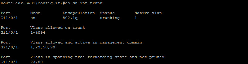
We can clearly see here that the Vlans in the diagram have been configured on RouteLeak-SW01 already. Since RouteLeak-SW01 is the VTP Server, it should sync with the VTP client.
Let’s configure the trunk links on the other switches. Refer to the “Trunk Link” article for more details.
Now that we have our trunk links, let’s start configuring VTP. the following are the steps we will take:
-Configure the domain name
-Configure the version (We will use version 2 for this example)
-Configure MD5 authentication
-Set the mode
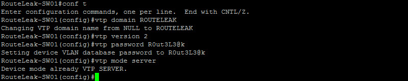
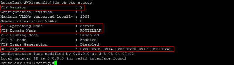
All right, that was easy… let’s run the “sh vtp status” to make sure everything is good.
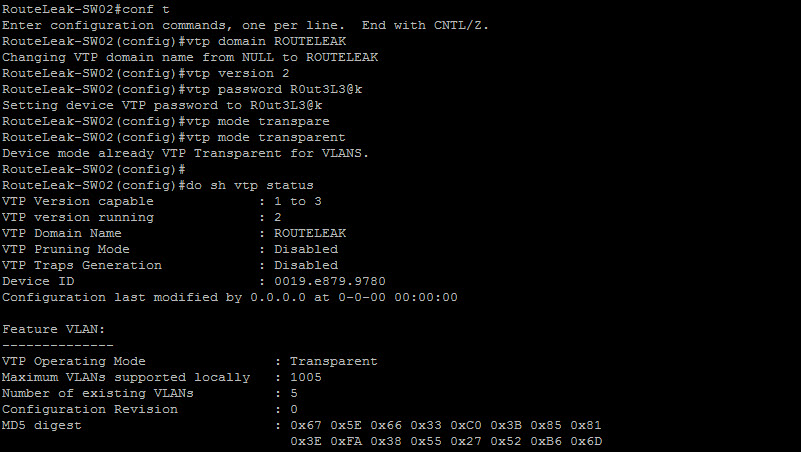
Now that we have RouteLeak-SW01 as the VTP server, let’s run the same commands on RouteLeak-SW02 and RouteLeak-SW03 except the “vtp mode” command. RouteLeak-SW02 will be in transparent mode and RouteLeak-SW03 will be in client mode…
Let’s configure RouteLeak-SW03 in client mode…

Ahh ! Here you can already see that we have 8 Vlans on RouteLeak-SW3. It seems that the switches synced already. Let’s check the vlans on each switch…
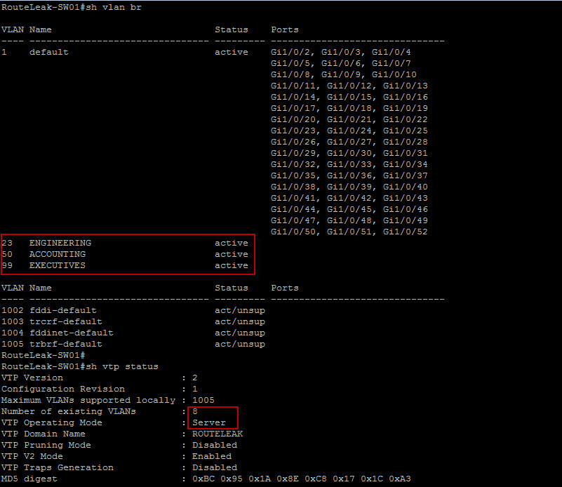
RouteLeak-SW01 is definitely the VTP server with a total of 8 vlans. Let’s check RouteLeak-SW02…
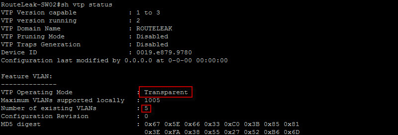
RouteLeak-SW02 is in fact in Transparent mode and has only 5 vlans which are vlan 1, 1002, 1003, 1004 and 1005 (Default). We can safely conclude that this switch did not sync with the VTP Server. Let’s now check RouteLeak-SW03…
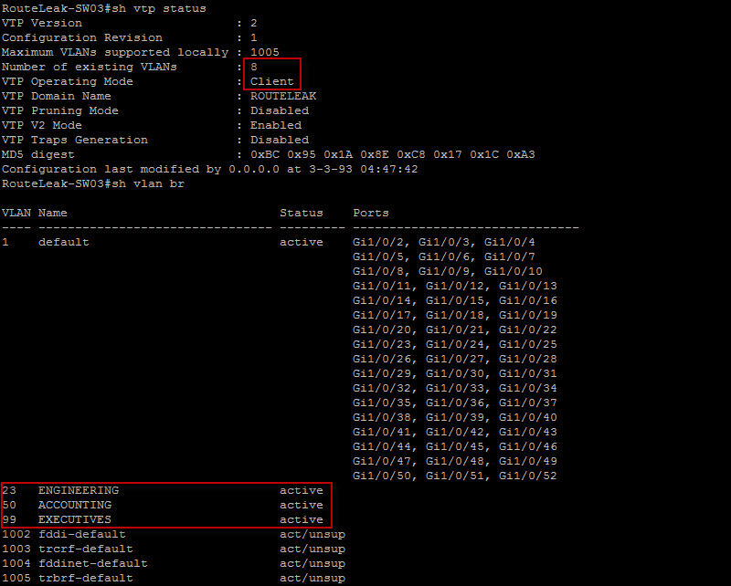
Looks like we are good. The switch successfully synced with the VTP Server and we can see the vlans have been transmitted to RouteLeak-SW3 from RouteLeak-SW1 through RouteLeak-SW02. Note that the transit switch did not installed the Vlan information but just transmitted it to the VTP client.
Quick Tips: Be extremely cautious when adding a switch that has been in your network before adding it back to your environment as the switch may be running in either server or client mode (Version 2) and has a higher revision number. It will potentially wipe your vlan configuration across your VTP domain. Reset it by changing the domain name to something else and set the mode to transparent first.
That completes this topic… I’ll talk to you guys later.
 Hello I'm Pape. My friends call me Pop. I'm CCIE #48357. I enjoy my field and love to share it with others. I love to write so I'm sharing my blog with you.
| M | T | W | T | F | S | S |
|---|---|---|---|---|---|---|
| 1 | 2 | |||||
| 3 | 4 | 5 | 6 | 7 | 8 | 9 |
| 10 | 11 | 12 | 13 | 14 | 15 | 16 |
| 17 | 18 | 19 | 20 | 21 | 22 | 23 |
| 24 | 25 | 26 | 27 | 28 | ||
Hello Jacqueline,
Thanks for the heads up 🙂 I’ll check it out.